This thread has been locked.

If you have a related question, please click the "Ask a related question" button in the top right corner. The newly created question will be automatically linked to this question.

TPS65400: Output 3 still giving out of ~1.8V when disabled ( ENSW3 pulled low)

Part Number: TPS65400

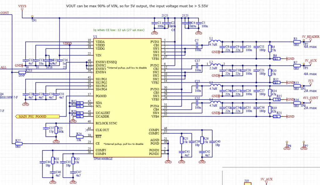
We use the TPS65400 in one of our designs with all 4 outputs used.

P1: 5V /4A

P2: 5v / 4A

P3: 3V3 / 2A

P4: 4V1/2A

Vsys 12V

Initially P1,P2,P3 are disabled by pulling ENSW1,2,3 low.

P4 is enabled by leaving ENSW4 and CE floating.
P4 output is 4V1 and P1,P2 are both 0V as expected.
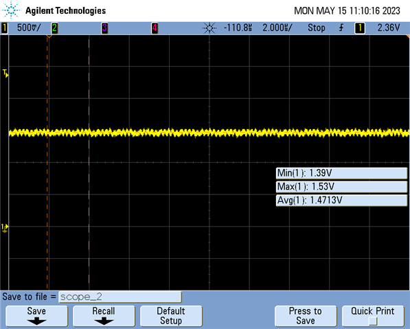
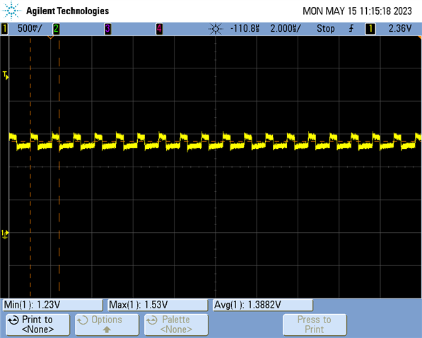
But P3 gives out a voltage of ~1.8V, although it is disabled.
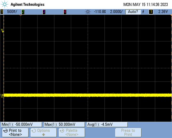
When P4 is also disabled by pulling ENSW4 low, the 1V8 on P3 drops to 0V.

When powering up the system, P1,P2,P3 are enabled via ENSW1,2,3.
Then P3 give out a voltage of 3V3 as expected.

We disconnected the P3 completely from the system (by removing R13 from the circuit) and still got the 1V8 on output of P3.

Is there any explanation for this behaviour?
As we are now experiencing problems because the voltage stays at 1.8V when shutdown, keeping some part of the system in and undefined state.

Thanks,

Rowan.


  • Hi Rowan !

    1. Could you pls help check whether the device is switching when 1.8V on P3 is existing? It is better to probe the waveform of SW3 with 2us/div.

    2. Could you probe the waveform of ENSW1-4, When P4 is enable and p1-3 is disable and P3 show 1.8V.

    3. Is this device programmed by you? I mean that did you change the internal configuration by PMBUS?

    4. Could you confirm that all of your board has the same issue or some boards have, other's don't have?

    Shuai

  • Hi Shuai,

    Thanks for the response. See answers below

    1. SW3 is not switching. It looks like the 1.8V (which is actually somewhere between 1.4-1.9V on different devices) is supplied directly from SW3.

    SW3 when only p4 enabled

    2. ENSW 1-3 disabled:

    ENSW1-3 disabled

    ENSW4 enabled:

    ENSW4 enabled

    3. No. The I2C bus is not connected

    4. Yes, i check 10 boards. All having this issue. Although the voltage is different between the devices. In range of 1.4-1.9V.

  • Hi Rowan!

    It is possible related to layout. Because I see that the ENSW4 be heavily coupled. (You can see some pulse waveform which looks like SW coupling)Could you pls provide the layout to review?

    Shuai

  • ENSW4 is floating (relying on the internal pull up)

    Are screenhots below oke for you to review? 


  • I tried connecting the ENSW4 to VDDD (3.3) to make sure the ENSW4 has a good enable signal. But this did not solve the problem on SW3.

  • Hi Rowan!

    1. Just roughly take a look by screenshot, I only find there some signal trace is too close to the inductor.

    Could you send the whole Altuim designer file for details?

    2. I am just wondering whether the device has been damaged during the previous operation (connect you load). If we pick up one new board which haven't been power on yet, and disconnect the load, let all 4 rail operate at zero load, will the issue still exist?

    3. Would you mind check the voltage of SW1-4, to observe whether the voltage is out of spec?

    3. Another suspicion is whether the issue is related to the CH4's loading or the input voltage. If we reduce the loading and the input voltage, will the issue still exist?

    Shuai

  • Hi Shuai,

    We found the problem, or actually a combination of problems which made is a bit harder to find.

    At the end it was, as we initially expected, a leakage voltage from somewhere else on our board. But apparently our switcher chip on which we where measuring was also damaged (probably due to our measurements).and was also supplying around 1,4V on SW3. which did confuse us in getting to the right solution.

    Thanks for your help.

    This issue may be closed.