This thread has been locked.

If you have a related question, please click the "Ask a related question" button in the top right corner. The newly created question will be automatically linked to this question.

LM5023: short circuit protection issue

Part Number: LM5023
Other Parts Discussed in Thread: SE555, LM555, NE555
hello, 
I made a small prototype that implements the scheme shown in the figure below to convert an input 48Vdc (40Vin-60Vin) into 245Vdc for 65W of power.

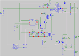
 As you can see, the LM5023 IC power supply is isolated from the primary 48Vdc power supply and the VSD pin is left floating. I encountered the following problem. When I apply a short circuit on the output, the power mosfet continues to be driven with a short duration pulses, causing the mosfet to overheat very quickly.

Not being able to use the auxiliary winding to power the IC, how can I fix this?
  • Hello Franco, 

    Thank you for your interest in the LM5023 QR flyback controller.

    Reviewing your schematic diagram, I see that the polarity of the primary winding of the flyback transformer is backwards with respect to the secondary outputs.  
    Since your schematic appears to be from a simulation software, rather than an actual PCB design software, I'm not sure if that problem has been fixed on your real board or not. 
    I am inclined to think that it has been corrected since your issue is with a short-circuit (SC) condition rather than normal operation. 

    In any case, the LM5023 incorporates Leading-Edge Blanking (LEB) to avoid erroneous short on-times from turn-on spikes.  This same blanking time (about 130ns) also becomes a minimum on-time for all switching pulses.  Shorting the output causes the feedback to become open-loop and the COMP signal rises to maximum in an effort to restore regulation to Vout.  This generates the short pulses that you observe at the MOSFET.  With only 10uH on the primary and 48V input, the peak current can rise fairly quickly during the 130ns blanking time.  But any additional turn-off delay (such as R-C filter on CS and excessively large MOSFET) will add to the peak current during these pulses. 

    Normally the AUX winding provides VCC bias power to the LM5023, and this power collapses during a short-circuit and leads to UVLO cycling.  This helps to keep the power loss down during a SC condition. Since you do not have this situation, but instead have a separate DC/DC source, you will need to design a circuit which detects the loss of AUX voltage over an extended period of time and use that to disable the DC/DC or reset the soft-start to mimic the usual behavior.  

    Regards,
    Ulrich

  • thank you. 

    yes the drawing has wrong polarities. The circuit works as specified. The primary inductance is 25uH.

    could you suggest me a circuit that can perform the task you described to me?

    Thank you.

  • Hello Franco, 

    The built-in time-delay function in the LM5023 depend on VCC cycling through UVLO during an overload.  Since you don't have such a situation, a similar function can be externally applied, based on detecting pulses at the Auxiliary winding. 

    I suggest to use a 555-timer (such as NE555, SE555, or LM555) configured as an astable multivibrator to discharge the SS capacitor.  The R-C values for the timer are chosen to drive the 555 output high for a short time and to drive it low for a long time. When the 555 output is high, it back-biases a schottky diode to allow the SS cap to charge and the LM5023 to run.  When the 555 output is low, the LM5023 SS cap is discharged through the schottky diode to GND.

    As long as there are switching pulses of sufficient amplitude at the AUX winding, these pulses can drive another transistor that can keep discharging the timing cap of the 555.  This keeps the 555 output high and won't affect the SS pin.  During normal start-up, the AUX pulse amplitudes at first are naturally too low since VOUT does not reflect much voltage to Vaux, and so the 555 timer cap starts to charge up toward the THRES threshold.  Eventually, VOUT comes up and the Aux pulses can discharge the timer cap, keeping the 555 output thigh.       

    If there is an overload which pulls VOUT down, the Aux pulses are insufficient to keep the timer cap discharged, so it's voltage rises to the THRES level and the 555 output goes low, which discharges SS and shuts off the LM5023.  The 555 timer is set to have a long Low time to allow the switching MOSFET and other parts of the converter to cool off.  This Low state also must defeat the transistor that shorts out the 555-timer cap.  Once the Low time is over, the 555 toggles back to High and the timer cap is shorted to GND and the LM5023 is allowed to attempt to restart.

    If the overload is gone and Aux pulses appear, then the 555 cap stays GNDed and 555 output stays high and LM5023 continues with power conversion. If the overload is still present, then the 555 High time will elapse and go low for another extended period of time, and the cycle repeats. 

    That is my suggestion for your situation. 

    Regard,
    Ulrich