This thread has been locked.

If you have a related question, please click the "Ask a related question" button in the top right corner. The newly created question will be automatically linked to this question.

BQ25798EVM: Issues Encountered with BQ25798EVM Development Board(LED、Charge Mode Verification、IINDPM)

Part Number: BQ25798EVM
Other Parts Discussed in Thread: BQ25792EVM

Dear TI E2E Team,

I am writing to report some issues I encountered while using the BQ25798EVM development board. Specifically, I have encountered the following three problems:

  1. Despite following the 2.4 Test Procedure, the LED (D13) did not light up. Instead, when I installed the shunt in JP17, the LED (D13) turned on. Can you please explain why this is happening?

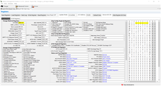
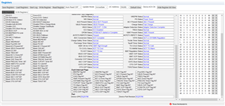
  2. I followed the 2.4.2 Communication Verification steps and set the parameters (including VSYSMIN, Charge Current, IINDPM, etc.). However, during the 2.4.3 Charge Mode Verification, the measured VBAT and REG1Cb[7:5] did not match my expectations. What steps can I take to resolve this issue?

  3. According to the specifications, the REG06_Input_Current_Limit Register should be set to 3000mA upon reset. However, no matter how many times I try to modify it, the IINDPM can only be measured at 1420mA or below. What can I do to fix this?

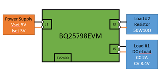
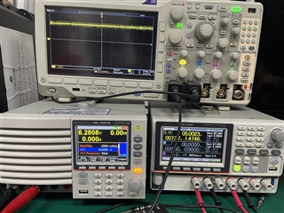
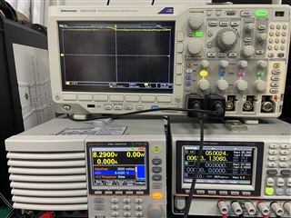
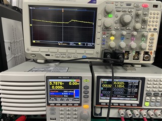
For your information, my PowerSupply is set at 5V and 3A. Load#1 is a DC electronic load set at 7.6V and 2A, while Load#2 is the only 50W 10-ohm cement resistor.

Thank you for your attention to these matters. I look forward to hearing from you soon.

Sincerely,

Freddie Jhneg

  • Hi Enshuo,

    Regarding 1, with the shunt on JP17 removed, charge is disabled so STAT LED D13 does not light up.  Per section 2.4.3 item 2 below:

    2. Reinstall the shunt on jumper J17 to enable charge • Verify Arrow right STAT LED (D13) is lit

    Regarding 2, SYSMIN sets the voltage at SYS if V(BAT) < SYSMIN.  What was the battery voltage at BAT when you tested?  The IINDPM (input current limit) is clamped by the resistor divider on ILIM_HIZ if the EN_LIM register.  Helpful hints in item 6 explains more:

    6. Helpful hints when changing voltages and register settings from those above during charge mode: • If increasing charge current or adding a load at SYS J3 terminal, you will likely need to disable the EN_ILIM bit using 8-bit register tab/Charger Single-bit Registers/REG14b[1] and increase the IINDPM register setting in 16-bit register tab/Charger Multi-bit Registers/REG06b[8:0].

    Charge current is clamped to 2A if V(BAT) < SYSMIN regardless of the charge current register setting.

    Also, if the watchdog timer expires, many of the registers including SYSMIN, charge voltage (BATREG) and charge current reset to defaults.  That is why item 3 of section 2.4.2 recommends as shown below:

    Prepare the charge mode charger register settings in the following way if not already set there by default: • On the 8-bit Registers tab in the Chip Config Single-bit Registers section – Change Watchdog Timer to disable

    Regarding 3, see 

    6. Helpful hints when changing voltages and register settings from those above during charge mode: • If increasing charge current or adding a load at SYS J3 terminal, you will likely need to disable the EN_ILIM bit using 8-bit register tab/Charger Single-bit Registers/REG14b[1] and increase the IINDPM register setting in 16-bit register tab/Charger Multi-bit Registers/REG06b[8:0].

    I hope this helps!

    Regards,

    Jeff

  • Dear Jeff,

    Thank you for your prompt response. I have followed your suggestion to close EN_LIM, and I am now able to modify IINDPM.

    However, I have encountered another issue while performing the Charge Mode Verification test according to the BQ25792EVM Spec 2.4.3 Charge Mode Verification. I have attached the test result for your reference, and it does not seem to match the measurement results mentioned in the Spec. Could you please advise if there is any known issue that could cause this discrepancy?

    Thank you for your help.

    Best regards
    Enshuo

    test result:docs.google.com/.../edit

  • Hi Enshuo,

    Unfortunately, I can't access google docs from work.  Can you send the data a different way?  

    Regards,

    Jeff

  • Hi Jeff,
    I copy to here, F.Y.I.

    2.4.3 Charge Mode Verification

     1.PowerSupply is set at 5V and 3A.

    Load#1 is a DC electronic load set at 7.6V and 2A

    Load#2 is the only 50W 10-ohm

    Measure/Verify

    Target

    Result

    REG1B

    reports all Normal

    meaning no DPM loops active and no WD timer fault (bits 7-4)

    VAC1 Present (bit2),

    VBUS Present (bit 0) and Power Good (bit 3)

    Reinstall  jumper J17

    STAT LED (D13) is lit

    enable charge

    VVBUS-PGND

    (TP23 and TP44)

    5.0 V ±0.2 V

    4.53 V

     VBAT-PGND

    (TP29 and TP46)

    5.0 V ±0.2 V

    7.6 V

    IBAT_SENSE

    (TP19 and TP20)

    240 mA ±60 mA

    732 mA

    REG1Cb[7:5]

    reports pre charge

    Fast Charge


    2.PowerSupply is set at 5V and 3A.

    Load#1 is a DC electronic load set at 8V and 2A

    Load#2 is the only 50W 10-ohm

    Measure/Verify

    Target

    Result

    VVBUS-PGND

    (TP23 and TP44)

    5.0 V ±0.2 V

    4.56  V

     VBAT-PGND

    (TP29 and TP46)

    8.0 V ±0.1 V

    8.1 V

    IBAT_SENSE

    (TP19 and TP20)

    500 mA ±50 mA

    622 mA

     IVAC1_SENSE

    (TP1 and TP2)

    900 mA ±60 mA

    2800 mA

    REG1Cb[7:5]

    reports pre charge

    Fast Charge

    3.PowerSupply is set at 5V and 3A.

    Load#1 is a DC electronic load set at 8.4V and 2A

    Load#2 is the only 50W 10-ohm

    Measure/Verify

    Target

    Result

     VBAT-PGND

    (TP29 and TP46)

    8.4 V ±0.1 V

    8.3 V

    IBAT_SENSE

    (TP19 and TP20)

    0 mA ±10 mA

    0 A

    REG1Cb[7:5]

     reports termination

    Fast Charge

    Thank you for your help.

    Best regards
    Enshuo

  • HI Enshuo,

    In general, when using an eload set to constant voltage to simulate a battery, the eload only clamps the voltage to the set value.  I recommend using a parallel power supply so that the battery charger sees a starting voltage, below the eload set value.  Also with a 10 ohm load on SYS, the charger will pull more input current to drive the SYS load and then, how ever much is left so to charge the battery.

    Regarding 1 above, the charger is correctly in fast charge not precharge because the battery voltage is at 7.6V which is higher than the VBAT_UVLO value, which defaults to a fixed % of BATREG below 7.6V.

    Regarding 2, if ICHG register is at 500mA, I can't explain why the charge current is above that value.  But, the higher input current is due to the 10ohm load on SYS.

    Regarding 3, if charge current isn't flowing, I expect termination, unless termination is disabled.

    Regards,

    Jeff

  • Hi Jeff,

    Thank you for your support with my previous issue. Your help has been greatly appreciated.

    As shown in the attached image, even after enabling EN Termination, I am still confused about the above Regarding 3.

    Thank you for your time and attention to this matter.

    Best regards,
    Enshuo

  • Hi Enshuo,

    Can you retake the screen shot above, showing all the status and fault registers and simply copy and paste into the post?  I can't open the figure above.

    If one of the DPM loops, like IINDPM or VINDPM or thermal regulation, are engaged because the SYS load is taking all of the input power and not leaving enough to meet the set charge current, then termination is disabled.  Could that be the issue?

    Regards,

    Jeff

  • Hi Jeff,

    I have attached two screenshots showing the e-load set at 8.4V. The incorrect registers are the Charge Status, which should be "Termination," but it is currently displaying "Fast charge." Additionally, following your previous advice, I noticed that the VSYS Status is indicating "NOT in VSYSMIN Regulation." Could this be a potential issue?

    Thank you for your attention to detail.

    Best regards,
    Enshuo


  • Hi Enshuo,

    No.  VSYSMIN is only when the battery is discharged below the 7V SYSMIN setting.  Can you enable the ADC, do a register read and take a screen shot of the 16-bit tab?  Is your eload sinking current?  In the past, I have had trouble with eloads as battery simulators.  Can you provide an oscilloscope shot of VBUS, SYS and BAT?

    Regards,

    Jeff

  • Hi Jeff,

    Thank you for your continued support and guidance. I appreciate your prompt response.

    Regarding your suggestion to enable the ADC register, I have made the necessary adjustments. Additionally, I can confirm that the e-load does have a current supply.

    Please note that I have not yet added the second power supply due to some issues. Currently, I am only using the e-load at J5.
    I have attached the configuration diagram and oscilloscope shot of VBUS, SYS, and BAT for your reference.

    configuration diagram


    VBUS


    VSYS


    VBAT


    I look forward to your further assistance in resolving these matters.

    Thank you for your attention and support.

    Best regards,
    Enshuo

  • HI Enshuo,

    BAT is reaching regulation as if there is no battery connected.  I think the problem is the eload.  It should be sinking current and clamp its voltage to the CV setting.  I am not familiar with that model of eload. I suggest disconnecting the eload from the charger board and then connect to a power supply to determine how to get the eload to clamp to the CV setting.

    Jeff