This thread has been locked.

If you have a related question, please click the "Ask a related question" button in the top right corner. The newly created question will be automatically linked to this question.

TPS63700: Cold Start at low current levels

Part Number: TPS63700

While testing the TPS63700 we have found at low current values 10-15mA the device will not self start at minus 40 deg. C. The load is highly capacitive, but even a rapid shutdown/restart will not recover the supply (i.e. the caps have not had time to discharge). If the device enters discontinuous conduction mode(DCM). We are using a 10uH inductor with 4 filter caps of 4.7uF, an input of 5.3V and an output of -11.6V. HAs anyone had cold start problems with this device?

  • Hi  Chris,

    I have not met similar behavior before. is it ok if you restart the device after a long waiting time?

    Regards

    Tao

  • Restart does not clear the power "off" condition. Only raising the temperature. It seems cold start is very load depended. 

  • Hi  Chris,

    i mean is it ok that you cut off your power supply for a longer time (may be several minutes)  then re-connect your power supplly?

    Regards

    Tao

  • As long as the DUT is at -40deg, the supply will not start under any conditions, load or no load. It has nothing to do with "time".

  • Hi Chris,

    Tao is out of office and he will reply you tomorrow.

  • Hi  Chris,

    you are not able to get any waveforms at -40deg. right?

    From my side, i will  check based on our EVM, could you share your schematic here?

    Regards

    Tao

  • May I suggest we revert to your eval board TPS63700EVM-139 which also behaves erratically at low temp (and quite similarly to our board). In the lab in open air, when the eval board is cooled sufficiently (to approx. -20 deg C, with a few brief shots of freeze spray) the output starts to droop and waiver about. After a few minutes as the board returns to above 0deg C, the output is still erratic and wavering about; it takes about 5 min. for the chip / output to return to normal and for most of this time the board is above 0 deg C. The main difference between our board's behaviour and the eval board is that ours sometimes shuts down for a few minutes before restarting (actually Vout drops to near 0V; there is still PWM switching activity but very little pulse density / energy developing); whereas the eval board did not seem to shutdown, just Vout waivering typically between -8 to -10V, then returning to normal.  Attached shows waveforms of our board during this sequence / event. In one waveform, Vout is captured at very slow sweep over several minutes starting from when the freeze spray is applied; in the other, the SW pin is captured at the time the chip appears to shut down (Vo is almost 0V) which occurs a couple of minutes after the freeze spray application . Probing the other pins on the chip during this event showed all normal signals / levels (including VREF COMP and FB pins) so I have no other evidence of ill behaviour by the chip. 

  • Hi Marcello,

    thanks for your detailed description. I am sorry that i did not start my bench test because some business traveling and personal reasons. i will feed back next week.

    According your description, the abnormal behaviour can be observed with EVM(no additional caps) and in light load(10mA is ok?), right?

    Regards

    Tao

  • No - most of my testing was done with 40mA up to a max of 200mA. I would suggest you test it at 100mA which is well within the chip capability in this cct. I dont know if our application will push it past 100mA anyways.

  • And no additional caps were added, you can test the eval board as is.

  • Hi  Marcello,

    Got it, conditons double-check.

    • based on EVM
    • 100mA output current and no additional caps
    • cool down with  freeze spray(impossible to control the actual operating temp,  just lower than minus 20℃)

    Any other comments about the consitons?

    Regards

    Tao

  • Hi  Marcello, Chris

    Test set-up as below:

    • Vin=5.3V  Vout=-12V  Iout=100mA
    • Freeze Spray:CRC

    start-up in normal temperature  Yellow-Vin  Blue-Vout   Green-current of inductor

    Start-up in minus temperature Yellow-Vin  Blue-Vout   Green-current of inductor

    it is normal from my side, did i miss anything? you observed this issue based on EVM, right?

    Regards

    Tao

  • I was not testing startup on the EVM; I was testing it in steady state when freeze sprayed. While the EVM was running normally, I hit it with a few brief shots of  freeze spray, enough to get it down to -20C on the surface, and a few seconds after the output decayed by a few volts; and stayed like this and did not stabilize / recover for several minutes (more than 5 min.). Sometimes it appeared to be shutdown (Vout goes to near 0V but TPS is still switching a little bit , not actually stopped).

  • Hi  Marcello,

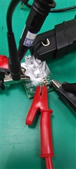
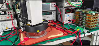
    I duplicate same phenomenon as your side with Freeze spray. But it is ok with thermostream even the temperature is -40. Bench test as attched picture.

    So, i expect the root cause is the condensed water droplets during the temperature rise, it will cause the impedance between the pins of the device to decrease. 

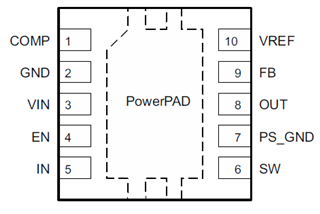
    Pin functions of TPS63700.

    Because the impedance of Pin OUT and FB decease, it will be some current flow from FB to Out and make the output voltage decrease finally.

    I tried to keep the device isolated with air during Freeze spray used, but our lab is lack of professional tools to do this, is it possible you can do this in your lab to confirm?

    Regards

    Tao

  • Interesting! It might be easier to seal the chip; if it is only pins 8 and 9  that are the problem I can put a drop of sealant to cover those pads on that area of the chip so moisture cannot get in. However the problem was first reported when we tested our system in a chamber (i.e ., not using freeze spray) so even if a sealant solves the problem I dont know that this is a viable solution (that we have to seal the cct. Also there should not be much condensation happening in our chamber but I will ask for details on how our chamber is operated.

  • Hi  Marcello,

    Thanks, hope this phenomenon will gone with sealed chip.

    But, i would like suggest you can seal the whole chip first, because i am not sure the root cause is Pins 8 and 9, just suspects.Sweat smile

    Which can be confirmed from my side is that this phenimenon has nothing to do with ambient temperature.

    Regards

    Tao

  • We have crazy glue here (Cyanoacrylate) but I don't know how it will react to freezing. It flows well so when I pour it over the chip it should cover it well enough - but I wonder if it will crack when I freeze it. Have you used this type of adhesive as a sealer? I only have one eval board here so I must be careful to not damage it.

  • By the way I don't understand what VOUT (sense pin) does or why it is necessary. The block diagram of the D.S. shows it goes to the 'Control logic' block but what effect does it have there? The FB pin (and its external resistor divider) are what is used to set the output voltage anyway.

  • Hi  Marcello,

    A simple way to understand is that you can consider there is resister in parallel with up resister of divider(the resister connect from out to FB),  because of the water droplets during temperature rising. 

    Have you used this type of adhesive as a sealer?

    i am afraid we do not have any similar material in our lab now.  in case device damaged during your bench, could you ask another EVM from https://samples.ti.com/store/?

    Regards

    Tao

  • I re-tested the same eval board with the chip 'sealed' (I used the  Cyanoacrylate) and found that sealing the chip solves the problem: the output is now stable with freeze spray applied, to -20C (and lower). But the test department here says there is no condensation in the chamber; so there is anomaly here; if there is no condensation in the chamber then the chip should not have failed. We will have to further investigate the situation with the chamber.

    Thankyou for your suggestion in sealing the circuit!

    The question I raised about the function of the VOUT pin and how it affects the control block still remains. How does this pin affect the control block?

  • Hi  Marcello,

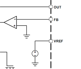
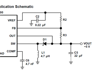
    According the block and the current balance at FB node, you can got an equation as below.

    Vref/R2=-Vout/R3+Ileakage.

    Here, leakage current means the current caused by the condensation. during the rising edge of ambient temperature, the leakage current becomes bigger one. Then Vout drops.

    Regards

    Tao