This thread has been locked.

If you have a related question, please click the "Ask a related question" button in the top right corner. The newly created question will be automatically linked to this question.

LP876242-Q1: How to config the power-up sequence TinstX

Part Number: LP876242-Q1
Other Parts Discussed in Thread: AM2732, TIDA-020047

Hi,

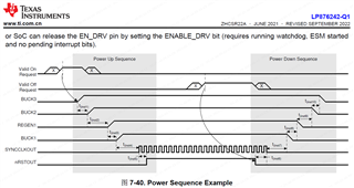
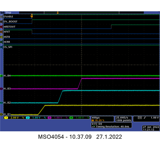
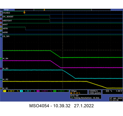
LP87624 spec mentions the time between buck1-3 enable and disable,but there is no detail description baout the TinstX.

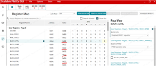
We want to know how to configure TinstX.

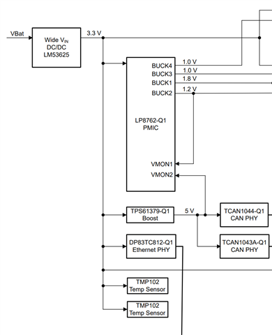
This pmic is dedicated for Dual AWR MMICs cascade application,is there recommended setting for this application,just like LP87524P?

Thanks!

  • Hi Wesley,

    The device expert is currently out of office due to a national holiday in Finland. Please expect a delayed response.

    Regards,
    Megan

  • Hi Lei,

    The above power sequence figure is generic and see below actual power sequence. The relative difference between BUCK1-3 is of 500µs for startup sequence and 100µs for shutdown sequence. 

    Best regards,

    Ishtiaque Panhwar

  • Hi Ishtiaque,

    Thank you for support!

    In our application, just like reference design https://www.ti.com/tool/TIDA-020047  for the dual MMIC and with AM2732, AM2732(MCU) is powered by LP876242, so LP876242 BUCK1,2,3 need to be enabled when power on. In other words, the BUCK could not enabled by AM2732 through SPI or I2C in this application.

    Please help confirm only rewirte these registers below in the .bin file could make this change or not.

    0x0004 = 0x23
    0x0005 = 0x25
    0x0006 = 0x23
    0x0007 = 0x32
    0x0008 = 0x23
    0x0009 = 0x2a
    0x000a = 0x23
    0x000b = 0x2a
    0x000e = 0xb2

    Thanks!

  • Hi Lei,

    I actually couldn't understand your question what do you mean by BUCK could not enabled AM2732. 

    There is connection between AM2732 with PMIC LP876242 through SPI. So, if it is possible through AM2732 to change the bucks then it can be. But I guess I need more clarification here. 

    So what do you want to change here. 

    Best regards,

    Ishtiaque Panhwar

  • Hi Ishtiaque,

    AM2732 is powered by LP876242 in our design, if the BUCK is disabled under default setting, then AM2732 is on power off condition and could not work or control LP876242.

    This application is same as reference design https://www.ti.com/tool/TIDA-020047, but different from LP876242 EVM that power the MCU with dedicated power supply.

    So we need the buck1,2,3 enabled under default setting,maybe the NVM configuration for TIDA-020047 could meet this requirement.

    Thanks!

  • Hi Lei,

    Let me confirm you by tomorrow but to my understanding they EVM NVM can be used for the reference design but I will check and get back to you. But reference design NVM can be programed on EVM as well. 

    Best regards,

    Ishtiaque Panhwar

  • Hi Lei,

    The NVM provided by email should work with reference design. Only difference is the I2C interface configuration. So, if you have similar design as is reference design with I2C interface then, it should work. Then you do not need to make any changes. 

    Best regards,

    Ishtiaque Panhwar 

  • Hi Ishtiaque,

    Thank you for confirmation!

    After loading the dedicated NVM to LP876242, the BUCK1 to 4 output could not be tested with multimeter, and the registers 0x04,06,08,0A=0x22, that means BUCK1 to 4 disabled. So, how to enable BUCK1 to 4 with the NVM, if there is some trigger conditions?

    Thanks!

  • Hi Lei,

    After loading the NVM, check if the device is enabled through GPIO4. Additionally, VMON1 (GPIO7) should be provided 1V2 from BUCK2 and VMON2 (GPIO8) should be set 5V as is in reference design. If the VMONs won't get supply then the device will turn off. 

    Best regards,

    Ishtiaque Panhwar

  • Hi Ishtiaque,

    You are right. VMON1 and VMON2 must be connected to 1.2V and 5V, or the BUCKs will turn off.

    Then I have a question, the VCCA_VMON_CTRL is 0x21 in register map, which means VMON1 and VMON2 are disabled, whether VMON1 and VMON2 diagnostic effectively?

    If there is no 5V in radar system, as CAN transceiver not used,how to mask the VMON2 related diagnosis?Another solution is connect with and monitor 1.8V(BUCK1 output),how to change VMON2 setting?

    In the reference NVM,the VMON2_PG_LEVEL is out of VMON2_RANGE(VMON2_PG_WINDOW register), is this correct?

    Thanls!

  • Hi Lei,

    If you want to disable VMON1 or VMON2 then it needs to be new custom NVM and for that it business case needs to be approved by the marketing team. 

    If you want to use exiting catalog OTP then, it needs VMON1, VMON2 and enable drive enabled. 

    And following is probably bug in the GUI,

    When I am looking into the register map, VMON2_PG_SET should be 0x5F (see below) when the range (3.35V-5V) is selected. 

    And it is also in the data sheet ( P No. 47) as below.

    Best regards,

    Ishtiaque Panhwar