This thread has been locked.

If you have a related question, please click the "Ask a related question" button in the top right corner. The newly created question will be automatically linked to this question.

LM74502: gate/source drive protection?

Part Number: LM74502

Dear TI support team

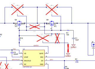
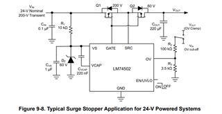
The LM74502EVM user's guide shows on the schematic on page 6 the elements Q5, D1 and R1, but there is no explanation about this optional circuit, also in the datasheet this option is not mentioned at all.

Do you have an app note explaining this circuit in detail including the requirements for these three parts?

Thanks!

Regards

Urban

  • Hi Urban,

    Thanks for reaching out to us. 

    The additional components Q5, D1 and R5 (in EVM schematics) are only required while using LM74502-Q1 in surge stopper configuration as shown in datasheet image below. 

    In the surge stopper configuration shown above, there is R1 and Cvs connected to the VS pin which creates a RC delay between the input voltage and the voltage seen at the VS pin. 

    So, the NPN transistor (Q5 in EVM schematics) on the GATE shorts GATE to SRC pin when SRC pin reaches to -0.7V (VBE of NPN transistor) This turns OFF external FETs even though VS pin slowly discharging through 10kΩ resistor connected to the VS pin in surge stopper configuration.