Hello,
I am using TPS54340B-Q1 to convert 24V DC to 5V DC the load current is 3A.
For 5V output i am getting 9.3V at the output.
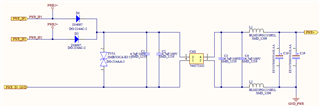
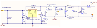
Please help me to rectify the issue, Refer to the below schematic.
Hello,
I am using TPS54340B-Q1 to convert 24V DC to 5V DC the load current is 3A.
For 5V output i am getting 9.3V at the output.
Please help me to rectify the issue, Refer to the below schematic.