This thread has been locked.

If you have a related question, please click the "Ask a related question" button in the top right corner. The newly created question will be automatically linked to this question.

BQ34Z100-G1: Why is QmaxPassedQ cleared at full charge?

Part Number: BQ34Z100-G1
Other Parts Discussed in Thread: GAUGEPARCAL, BQ34Z100, BQ34Z100-R2, GPCCHEM, BQSTUDIO

Hi them.

We've been trying to learn the BQ34Z100-G1 for a few weeks now with no success.

I reviewed the settings and ran it, and I was able to detect full charge by the taper current.
I was able to confirm that the VOK bit changed from H to L during relax mode.
However, the UpdateStatus still 04 and the learning could not be completed.

After some investigation, QmaxPassedQ and QmaxTime QmaxDOD0 are cleared to 0 when full charge is detected (FC=H).

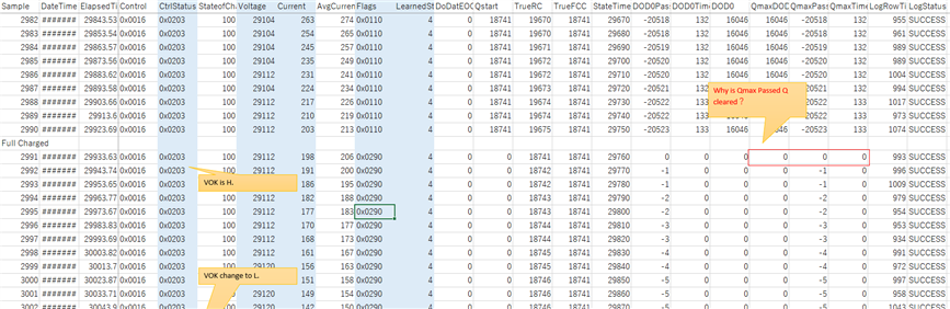
Why is this occurred?
We understand ImpedanceTrack clears it when it integrates QmaxPassedQ.

I need some advice to make it successful.

We believe that it should be held while VOK is high.Because it is integrated when VOK is L.

Write additional information below

  • BQ34Z100-G1 (FW v0.16)
  • 8P1S LiFePO4 40000mAh (40Ah)
  • CHEM ID = 0435
    I think that this is correct because it was below reported by GAUGEPARCAL.
    Best chemical ID : 435 Best chemical ID max. deviation, % : 16.86
  • FC_Set = -1. (Because FC bit will be H before full charged actually)
  • TCA_Set = -1. (I was told that it was detected that charging was complete before it was fully charged.)

20230515.log

setting_20230515.gg.csv

  •     The Qmax supposed to update at VCT, can you upload the srec file you used for learning? I need to check all parameters

  • Hi Steven.

    Here is the srec file we are using for learning. I would like to know what the cause is.

    8475.0100_0_16-bq34z100G1.srec.txt

  •     I think I finally found the cause of your issue, what you observed regarding QMaxPassedQ and DODPassedQ clear at full charge are as expected. VOK keep set at the same time is also normal, all these are expected behavior for for the cell with LiFePO4 chemistry.

       The issue is that you should not set Flash Update OK Cell Volt to 3838mVolt, which is too high for Qmax in dataflash to be updated, for LiFePO4 battery, this should be set lower than regular Li-ion Cell, I think even 2v shall be appropriate for your configuration of 8S1P

       Please also be noted that another parameter of CC Threshold is way too low to the capacity of the battery

  • Hi Steven.

    Thank you for your answer. And sorry to late my reply.

    We try to learning process again after change its parameter.

  • I have a question.

    Flash Update OK Cell Volt was determined according to datasheet. SLUSBZ5D datasheet describes below at 8.2.2.1.3.

    Following the successful voltage calibration, calculate and apply the value to Flash Update OK Cell Volt as:
    Flash Update OK Cell Volt = 2800 mV × Number Of Series Cells × 5000/Voltage Divider.

    Then we calculated its  parameter.

    2800×8×5000/29179=3838

    We think that the Flash Update OK Cell Volt is simply threshold ignore Voltage Divider. Because formula of Flash Update Cell Volt contains Voltage Divider parameter.

    Is this incorrect?

  •      Such calculation will get the raw ADC reading, but this supposed not to be used to compare with actual value used in FW, please try using 2800 see if you can get Qmax updated by repeating the learning cycle.

        I will need to check with internal team to get this clarified.

  • Hi Steven.

    I understand.

    We started the new learning cycle with Flash Update OK Voltage = 2000. I will post the results when I have them.

  • Hi Steven.

    I report the result however learning cycle is running.  This learning cycle is going well. Update Status  of Gauge was changed to 0x05.
    I continue my learning cycle. Since VOK is not 0, we plan to proceed with the discharge cycle after investigating the cause.

    • Flash Update OK Cell Voltage = 2000
    • Quit Current = 100 (This indicate 300mA actually.)
    • Chg Current Threshold = 150 (This indicate 300mA actually.)
    • Dsg Current Threshold = 200 (This indicate 400mA actually.)

    Thanks for the proper answer.

  •     After aligning with the internal team, it is confirmed that the description in the datasheet is not correct, Flash Update OK Cell Voltage shall be the averaged cell voltage under which the flash update is allowed to happen.

       For LiFePO4 battery, the QMax update happens at the end of charge, i.e., VCT, once this happened, VOK is cleared briefly, but set again immediately, so what you are seeing is the VOK keeps setting during Qmax update, which is as expected.

  • Hi Steven.

    Thanks to your answer, I was able to confirm that the learning process is fine.

    I'll post the results when the discharge process is complete. I think it will take some time.

  • Hi Steven.

    The learning cycle is successfully finished. Thank you for your follow up.

    Before the learning cycle succeeds, here's what I did wrong. I would appreciate it if you could help someone solve the problem.

    • The datasheet I was checking was incorrect.
      Please check the FW version of the BQ34Z100 you are using.0.16 is BQ34Z100-G1. 2.x is BQ34Z100-R2.They are the same hardware.
    • Failed to get CHEM ID.
      For detailed information, see datasheet. (or GPCCHEM )
      It was necessary to have a constant voltage at full charge and a stable voltage during the relaxation period after discharge.
      If you use bqStudio logger, elapsed time format may be incorrect.(GPCCHEM require integer, but logger output real value with bqStudio ver.1.3.101)
    • BQ34Z100-G1 needed scaling to use large capacity battery.
      If you use BQ34Z100-R2, you may be able to use the scaling function. I didn't use -R2 because I didn't know how to use large capacity.
      We use 40Ah battery (8S1P). Scaling is required when using 29Ah or more with BQ34Z100-G1.
      For detailed information, see  SLUA760 application note.
      At our pattern, use scaling factor = 2.  Design Capacity =  40,000 / 2 = 20,000. Specify calibration current is 1,000[A] when actually current is 2,000[A].
    • Voltage calibration failed.
      BQ34Z100-R2 (FW Ver.2.01) failed with bqStudio 1.3.101, but BQ34Z100-G1 (FW Ver.0.16) succeeded.
      Maybe it's just my environment.
    • I didn't understand the procedure of the learning cycle.
      Initial setting -> IT_ENABLE -> Reset -> Discharge -> Relax -> Charge -> Relax -> Discharge -> Relax ?
      Or
      initial setting -> Discharge -> Relax -> IT_ENABLE -> Charge -> .Relax -> Discharge -> Relax ?
      See SLUA903.
    • Learning cycle was failed with incorrect setting.
      If FC_SET is 100(default), gauge may detect full before end of charge. Need to detect FC by taper method. However this is my thinks It may incorrect.
      TCA_Set=-1. (I think this setting is necessary in this case. I'm a little unsure.)
      Cell Charge Voltage is used to Charge Termination. I have to set it, charge termination voltage / Number of series cells.
      Flash Update OK Cell Volt is incorrect. I have to set it simply voltage. (Not divide by Voltage Divider)
      I don't know much about Design Energy, but according to the information on the E2E forum, it was written that one cell should be set, or that it is not necessary depending on the Load_Mode.
      Quit Current, Dsg Current Threshold and Chg Current Threshold must set better value for system.

    Here is the log of the last successful cycle.

    20230525.zip

  •     Thanks for letting us know the success, and the summarize for the tests to be success.

        For voltage calibration for R2, a new build of R2 is to be released soon to have this issue fixed.

        For learning cycle process, both shall work, but please assure the status bit toggles as specified in the slua903.

        For the bits of FC_ET and TCA_SET configuration, in principle, it is not mandatory for learning cycle to be success. but  for LeFePO4 or NiMH batteries, it is suggested to set as the we you described above, otherwise, it could take a extreme long relaxation to get the voltage to be stable enough for Qmax update to happen.

        For G1, Design Energy is on basis of single cell voltage