This thread has been locked.

If you have a related question, please click the "Ask a related question" button in the top right corner. The newly created question will be automatically linked to this question.

LM5023: TL431

Part Number: LM5023
Other Parts Discussed in Thread: TL432, LMV431, , ATL432


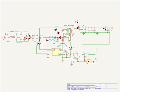
In the schematic diagram,(12V 5A), using the TL432, regulation is suitable up to 12V 2A; after that, the voltage drops significantly.
Replacing the TL432 with LMV431, the regulation is correct, with no more than a 3mv drop from 0 to 5A.
I need help with the circuit to work with TL432.
Thanks

  • Hello John, 

    Thank you for your interest in the LM5023 flyback controller, and other TI parts. 

    The LMV431 regulator requires much lower bias current than the TL432 does, so at full power, where the opto-current should be almost nill, the LMV431 bias current does not drive the opto enough to pull COMP of LM5023 down significantly.  However the TL432 typically needs over somewhere between 0.4mA to 1mA of bias current to function, so as the load increases and COMP current should decrease, it begins to starve the TL432.  So, the minimum TL432 bias current keeps the optocoupler on enough to pull down on COMP enough to affect regulation at higher load.    

    The solution is to provide a bypass path for the TL432 bias current by adding a ~560R resistor across the photodiode of the optocoupler.  
    1mA through this resistor drops only 0.56V which does not forward-bias the photodiode on enough to generate any significant current at the collector terminal. Hence, the LM5023 can deliver full power.  
    Note: the 1mA still has to be supplied through the 10K (R12) which will drop 10V, leaving only 2V across the TL432 which won't work.  So R12 should also be reduced in value to ~4.7K to provide some voltage headroom to the TL432. 

    An alternative solution is to substitute an ATL432 regulator in place of the LMV431, as this part also has a much lower bias current and may not need to have the extra bias resistor added to operate in the circuit.  Nevertheless, I recommend having a bias resistor around the photo diode in any case, to avoid any question with respect to CTR variations. 
    For the ATL432, the value of the bias resistor can be much higher than 560R ( such as 5.6K to 15K, depending...) due to the very low bias current needed.  

    Note: if one of these suggestions solves the problem, then the issue is with properly selecting and biasing the shunt regulator, not with the LM5023. 
    If that is the case, a different E2E forum can better support any follow-on shunt regulator questions.

    Regards,
    Ulrich

  • Hi Ulrich Goerke:
    Thanks for the quick and efficient response.
    It worked, and now it regulates from 0 to 5A.
    The output voltage changed from 11,997 to 11,945, but changing the resistance value will be easy.

  • Hi Ulrich Goerke:
    Thanks for the quick and efficient response.
    It worked, and now it regulates from 0 to 5A.
    The output voltage changed from 11,997 to 11,945, but changing the resistance value will be easy.