A related question is a question created from another question. When the related question is created, it will be automatically linked to the original question.
If you have a related question, please click the "Ask a related question" button in the top right corner. The newly created question will be automatically linked to this question.
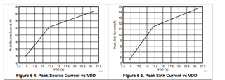
Unfortunately, it isn't spec'd. Generally, peak current can have a lot of variation, especially over temperature. The only data I have is from simulations (for UCC27511), which predict a typical peak source current of about 2.3A and sink of about 5.7A (for the 8A driver). I can't guarantee that the actual device will perform according to that though.
Another way you could look at this, is to use the specified rise and fall times at 4.5V in the datasheet. Using those numbers, you can find the expected rise/fall time and thus switching losses of your FET based on its Cgs, and never have to calculate with peak current. It is also a datasheet spec, so you can rely on its accuracy.
Lastly, if this is for a GaN FET, this is partly why our GaN drivers (such as LMG1020) are good for those FETs; they are optimized for drive at 5V rather than just allowing it. Here is a capture from the datasheet of UCC27614:
This is a 10A driver, but drops to about 4A at 5V VDD. LMG1020 being a 7A/5A may sound weaker than UCC27614 at first glance, but at 5V it is actually stronger.