This thread has been locked.

If you have a related question, please click the "Ask a related question" button in the top right corner. The newly created question will be automatically linked to this question.

TPS7A44: Output can't provide enough current

Part Number: TPS7A44

Hi,

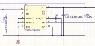
I designed a circuit with the TPS7A4433DGQR (3,3V fixed output.).

When the input Voltage is 20V I can draw up to 12mA on the 3.3V output before the Outputvoltage gets big bumps and soon breaks down. At 60V input I can draw up to 800uA till the same thing happens.

It looks like a thermal shutdow, but the surface temperature is not getting over 35°C. 

I got 100nF on Pin 10. 2,2uF on pin 1. MID_OUT is not used and got 10uF to GND. MVSEL1 and MVSEL2 are directly bound to GND.

If my load is very little everything is just fine.

Anyone got a similar behaviour?

Thanks for all advise and help.

  • Hi Florian,

    Can you share the schematic and layout of the LDO? The power dissipation at these conditions are not very high so I wouldn't expect it to get to thermal shutdown. 

    Can you also share waveforms of what you have described?

    Thanks,

    Nick

  • Hi,

    thanks for the quick respond. I hope these pictures can help.

    In the Schematics i wasnt sure if c37 is needed when MID_OUT is not used. After i got these Problems I added the 10uF Capacitor but it didnt change anything.

    The Enable Signal (green) is steady at around 4V all the time. When I increase the Input voltage (yellow) a little bit, with the same load, the output (blue) suddenly gets messy.

    Thanks for your help,

    Flo

  • Hi Flo,

    Thanks. This is definitely not a thermal issue; your board layout will definitely have better thermal performance than the datasheet thermal metrics. Furthermore, the waveform does not look like thermal shutdown. 

    FYI, the MID_OUT cap is necessary for stability. 10uF satisfies the 3xCOUT required minimum capacitance for MID_OUT. Can you take another waveform showing VMID_OUT as well? 

    Something else I noticed is that you only have 100nF on the input, unless there's more that I'm not seeing. The datasheet says that there's a minimum required input capacitor of 1uF, so this may be why your device looks like it's becoming unstable. See if replacing it with a 1uF cap solves the issue.

    Regards,

    Nick

  • Hi Nick,

    thanks for the response. 

    Is there a new Datasheet? I got the one from "NOVEMBER 2021" and there it says 0.1 μF.

    Here some pictures from the VMID_OUT (green), with Vout(yellow) and Vin(blue).

    I built five sample boards. Every board with the same issue. Guess its not a Problem with the ICs...

    Thanks for your help,

    Flo

  • Hi Nick,

    I am realy sorry. I made a mistake while soldering the 10uF capacitors to the MID_OUT. I checked the capacity only by measuring from pad to pad, not ic-pin to gnd.

    Now the capacitors are realy in place, the IC just works fine...

    Sorry for bothering you.

    Regards,

    Flo