Hello team,
Customer question translated with TI-Translator,
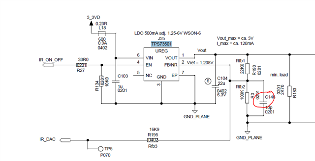
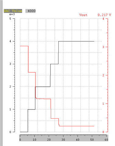
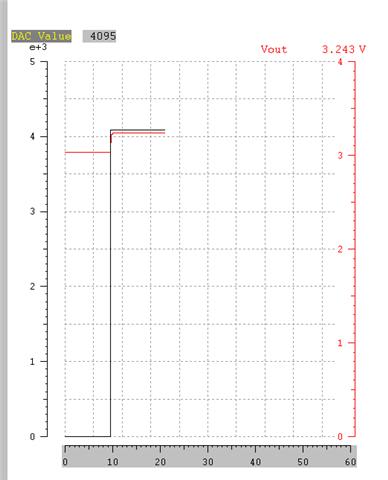
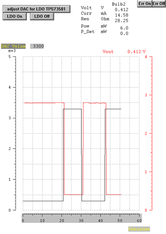
Today, a tricky question. I am using the TPS73501. I set the VOUT voltage with a DAC. The signal is called "IR_DAC". "IR_DAC" is generated with an 12bit DAC, max. 3.0V output. Setting range of the LDO about 0.2V.. 3.0V for Vout. In principle, this also works with 100% of all PCB's, if the DAC step size is not too large. In 99% of the PCB's, the step size of the DAC plays absolutely no role. The voltage IR_DAC can be switched from 0 to 3V and back to 0V. This works as often as you like with the 99% of the PCB's. Only the 1% of ICs worry me. If you select the increment of the DAC here too large, specifically approx. >2000 (i.e. IR_DAC from 0V to 1.5V and then again to 0V ), then this does not work for 1% of all ICs. The voltage Vout then goes to the operating voltage of the IC of 3.3V. A line will probably be conductive internally in the IC. (Parasitic thyristor ?) However, nothing is broken. However, the circuit always works in slightly smaller DAC steps, i.e. less than 1800 (i.e. IR_DAC from 0V to 1.3V). Maybe the problem will be solved if I increase the capacitor C148 ? But what would be a good value, which has no negative effects, but nevertheless solves the problem? And why do 99% of ICs always work? Can certainly be simulated. But does the simulation map reality exactly enough? The problem could also be solved by means of increment limitation, only that would be a SW change, but it is too late for that.
Appreciate an answer soon.
P.S. I'm at the FAE Summit this week.