This thread has been locked.

If you have a related question, please click the "Ask a related question" button in the top right corner. The newly created question will be automatically linked to this question.

BQ24650: Prevent BQ24650 leakage current

Part Number: BQ24650

Hi,

We implement code to prevent BQ24650 leakage current as described in TI document SLVA829.

The method we used was a Mosfet in the MPPT pin, and that works adequately.

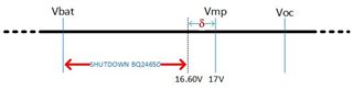
In the first test we set two values that are (95% x Vmp) and (90% x Vmp).

When the solar panel voltage rises above (95% Vmp) we remove the shutdown the BQ24650, and when it falls below (90% Vmp) we force the BQ24650 to shutdown.

In the measurements we made without solar panel (solar panel voltage = 0) , we found that the total consumption of the MPPT charger board remains the same, i.e. we did not measure any reduction in consumption as we expected.

We did a second test, where in addition to the condition of having the solar panel voltage less than 95% of Vmp, we only shutdown the BQ24650 when simultaneously the solar panel voltage was HIGHER than the battery voltage at that moment.

The measurements never showed a reduction in MPPT charger board consumption in the above described condition.

We have confirmed that the MPPT pin of the BQ24650 is forced to zero volt, when we shutdown the BQ24650.

In the tests we used a solar panel simulator, and a battery simulator to set the above values.

We don't understand why there isn't at least a slight reduction in current consumption when we shutdown the BQ24650 as described above.

On the other hand we don't know what the best algorithm to force and remove the shutdown from the BQ24650 is.
Is it any of the algorithms described above, even with another percentage of Vmp, or another one that we haven't used so far?

Reading the manual it was not clear how we can, in theoretical terms, calculate the current that the BQ24650 draws from the battery when the solar panel voltage is between Vmp and Vbat.

Any information and comments regarding the above described is welcome.

regards

Jose

  • Hi Jose,

    Can you confirm that the leakage current is going into the IC itself (either VCC, SRN or SRP pins) and not through smaller sized (<499kohm) resistors at MPPSET and FB?  If so, then can you confirm that VREF and REGN are going to zero when the MPPSET is pulled low?  If so, then you may need to add the Schottky and extra cap as shown below:

    Regards,

    Jeff

  • Hi Jeff,

    Thank you for your comments.

    We repeated all the tests, which I will now describe.

    The BQ24650 has a hardware-defined Vmp on the MPPT pin of 17V.

    We made voltage measurements between the SRP and SRN pins, and they are consistent with the different battery charging currents during the tests. 

    We programmed the battery simulator for 13.30V and the solar panel simulator for 15.15V.
    This way the solar panel voltage (15.15V) is in the middle of the range of Vmp (17V) and Vbat (13.30V).

    We measured 0V at the SRP/SRN terminals which indicates that there is no current, i.e. the battery simulator does not 'discharge' through the BQ24650.

    We varied the solar panel voltage between 17V and 13.30V, and there was never any discharge current from the battery simulator through the BQ24650.

    We removed the battery simulator and used a lithium battery with approx. 13.30V voltage, repeated the tests and the result was the same.

    Note that we have no diode in our circuit to prevent the battery discharge current.

    In above tests we never forced the MPPT pin to low, since we wanted to check the battery discharge by the BQ24650.

    We could not simulate a situation like the one described in the document we have already mentioned, where the battery discharges through the BQ24650 when the solar panel voltage is between Vmp and Vbat.

    It may seem strange that we have this concern when we don't encounter a problem, but the question is whether the problem will appear later in other conditions that we are currently missing.

    regards

    Jose

  • Hi Jose,

    The app note was inspired by customer complaint.  Since we released it, we haven't had any more complaints.  As long as the IC MPPSET is placed in HiZ mode, the IC pins go high impedance and do not sink current (other than nA pin leakage).  The big concern is SRP/SRN.  So, for max safety, I recommend the Schottky diode on the output as a redundancy.

    Regards,

    Jeff

  • Hi Jeff,

    The electronic board is already ready for production, so there is no point in changing it for this reason.
    This way we can only use the Shutdown control.

    The question that arises is which value close to Vmp we should use to remove the Shutdown.


    If the value is below Vmp it will have a voltage zone from that value until Vmp in that we don't solve the problem.


    If the value is above Vmp, and when we remove the shutdown, the BQ24650 will fix the voltage of Vmp and the code can again force the shudown and we will have the charge inhibited.
    All this due to the accuracy of the microcontroller ADC and the tolerance of the BQ24650 in setting Vmp.

    Do you have any idea what is the best concept to overcome the above problem ?

    regards

    Jose

  • HI Jose,

    The real issue is that the body diode across the Q1 high side FET provide a path from the battery to VCC.  If panel output voltage is above V(BAT) but below VMP, the VCC can draw in the mA range as if charge was disabled.  There is some leakage going into SRN too but it is in the uA range.

    VMP accuracy below is   but ignores resistor tolerance.  I assume you are using a second resistor divider off the panel and using the ADC to measure that voltage?  If so, worst case  +/-0.6% +/- 1% resistor tolerance, should be good enough.

    Regards,

    Jeff

  • Hi Jeff,

    I appreciate your comments, but I will try to be more concrete on the question to which we seek an answer.

    Our Vmp is of 17V defined by resistances of 1%, so that in the limit we can have 2% of error, that is a Vmp of 16.66V.

    Then we used the value of 16.60V to make the shutdown of the BQ24650 as shown in the below figure.

    The problem in this case, is that the zone represented as 'delta' will continue to consume current because we don't have the BQ24650 in Shutdown.

    So we don't see a way to make the algorithm more accurate, so that we don't have a zone in which the BQ24650 can consume current from the battery.

    It is on this subject that I would appreciate your comments.

    regards

    Jose

  • Hi Jose,

    I do not see how to prevent this delta.  You could use higher accuracy resistors to prevent it but it will still be there, just smaller.

    Regards,

    Jeff

  • Hi Jeff,

    Thank you for your answer.

    We are going to do some tests to see which is the best solution to reduce the impact of the described problem.

    regards

    Jose