This thread has been locked.

If you have a related question, please click the "Ask a related question" button in the top right corner. The newly created question will be automatically linked to this question.

BQ24171: Functionality Clarification

Part Number: BQ24171
Other Parts Discussed in Thread: BQ28Z620, CSD25402Q3A, CSD17313Q2

Hi all,

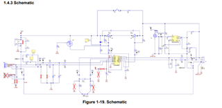
We are thinking about using bq24171 charger IC in our board where we will implement 3.7V 2850 mAh Li-ion battery.

Please clarify the following doubts regarding bq24171 charger IC. 

1. Required system load Power will be provided directly from adaptor right?

2. If battery voltage becomes 2.75V(Fully discharged battery). Will bq24171 isolate system load from battery?

3. If battery polarity is connected reverse, will bq24171 protects the system load? If not what is the solution?

4. Charger IC alone is enough or Do I need battery monitor, battery protector and fuel gauge. Can you provide one reference design where bq24171 is used with battery monitor, battery protector and fuel gauge.

Regards

Akilarasan

  • Hi Akilarasan,

    Regarding 1, yes.

    Regarding 2, no.  The charger expects the battery pack protector to open if the cells discharge that low. The BATFET that connects the battery to system has a body diode that allows current flow from battery to system.

    Regarding 3, no.  Most customers use a hardware keyed battery to prevent reverse installation.  Since current has to flow into and out of the battery, it is difficult to implement a circuit based solution to prevent reverse polarity plug in.

    Regarding 4, you need a protector at minimum.  I also recommend a basic a basic gas gauge to show how charged the battery is.  Unfortunately, I don't have a reference design.

    Regards,

    Jeff

  • Hi Jeff,

    Do I have to use battery protector IC for that battery polarity issue ?. If it is suggest me some.

  • Hi Akilarasan,

    The protector only protects the battery itself from over/undervoltage and over discharge.  The polarity issue is more to protect the charger IC and any other circuits directly connected to the battery from having negative voltage applied.

    Regards,

    Jeff

  • HI Jeff,

    As you mentioned  before I need one battery protector and basic gas gauge. I'm not sure how to choose. I will be using 2s cell. Below are my requirements.

    For Battery protector:

    1. It has to provide Overvoltage protection, Over discharge protection, UnderVolatge protection.

    For Fuel gauge :

    1. Mainly fuel gauge will monitor the charge in battery right? that functionality is enough.

    With this two requirements can you  please provide me a basic protector IC and gauge IC. I'm thinking about using this both with BQ24171.

  • Hi Akilarasan,

    I am not the expert on protectors and gas gauges.  So, I have moved this to monitor group first.  Then, hopefully, after that engineer answers they can move you to the gauge group.  

    Regards,

    Jeff

  • Hello Akilarasan,

    The BQ28z620 is a 2S gauge with integrated protections. 


    Regards,
    Jose Couso

  • Hi Jose,

    I checked BQ28Z620 eval board schematic where it is was not clear also there are some cross marks(schematic image attached below). I'm not understanding what it is. Can you please clear provide reference schematic.

  • Hello Akilarasan,,

    The the X marks in the schematic means "DNI" do not install.  That means those components are not installed on the board.

    Regards,
    Jose Couso

  • Hi Jeff,

    I have some doubts regarding BQ24171 Eval Board

    1. Working of reverse input protection circuit ?

    2. Functionality of BATDRV_n pin. Also setting Voltage divider for BATDRV_n ?

    3. Schottky diode B220A is used, Is it for reverse polarity protection for battery charger from battery?

    4. Battery Voltage is connected to AVCC pin, Does battery provides power to bq24171 when adapter is removed?

    5. In BOM, for some capacitors it is mentioned as OPEN . Does it means those components are not populated in board ?

    6. How much current will be consumed by bq24171, Consider a case where it is charging a battery at 1A charging rate?

    7. MOSFET CSD17313Q2 is used in eval board, but that part not available now and it is showing CSD25402Q3A as an alternative part. We can use CSD25402Q3A as alternative for CSD17313Q2?

    8. Battery will get charged in this condition : VBATT<4.2V, right? At what VBATT level, recharge will happen ?

  • Hi Akilarasan,

    Regarding 1, the circuit protects the IC from having the input power source connected in reverse.

    Regarding 2, BATDRV_n turns on the BATFET so that the battery connects directly to the SYSTEM.  The IC turns on the BATFET based on the voltage sensed by the OVPSET resistor divider.  It sets both input OVP and undervoltage.

    Regarding 3, no. The Schottky clamps the SW node to no lower than 0.3V below ground, in the event of switch node ringing below ground (from poor board layout). This also results in higher efficiency for the buck converter.

    Regarding 4, yes.

    Regarding 5, yes.

    Regarding 6, the Iq is shown below:

    Regarding 7, no CSD25402Q3A is a p-channel FET.  CSD17313Q2 is an n-channel FET.  I recommend 

    CSD17318Q2.

    Regarding 8, The recharge threshold is shown below:

    For VBATREG=4.2V, the recharge threshold is the feedback divider multiplier (4.2V/2.1V=2) times 50mV or 100mV.  So, recharge at 4.2V-100mV = 4.2V.

    Regards,

    Jeff

  • HI Jeff,

    Thanks for the response.

    Sorry, I meant whether CSD25402Q3A is an alternate part for CSD25401Q3?

  • Hi Akilarasan,

    Yes.

    Jeff

  • Hi Jeff,

    I'm going to use 103AT thermistor as it was suggested in bq24171 datasheet. Can you tell me how I can connect 103AT  with the battery.

    Do, I have to use a use a connector?. Or It has to be connected directly to battery ?

    Bcoz in eval board, 103AT has to be connected outside. So, I'm not understanding how to use it.

  • Hi Akilarasan,

    Most battery packs have a thermistor inside to monitor battery pack temperature. The TS pin uses the voltage on the thermistor to ensure that the battery is not charged outside of 0 - 60C range and to reduce charge parameters accordingly for JEITA WARM or COOL.  If you don't want to use a thermistor, you can use a resistor divider to set TS pin to 60% of VREF.

    Regards

    Jeff

  • Hi Jeff,

    If I don't want to use thermistor means i have to set 60% of Vref (3.3V)

    which means Vts should be 1.98V right?

  • Hi Jeff,

    It can be above 60% of vref or Below 60 % or exact 60%?

  • Hi,

    It needs to be between the TS thresholds from the datasheet below:

    Regards,

    Jeff

  • Hi Jeff,

    I'm not understanding this table.

    Consider I'm not going to use thermistor. In that case, what should be the voltage at TS pin.

  • HI Akilarasan,

    I recommend 60% of VREF=3.3V or 1.98V.

    Regards,

    Jeff