This thread has been locked.

If you have a related question, please click the "Ask a related question" button in the top right corner. The newly created question will be automatically linked to this question.

DRV103: DC Solenoid PWM

Part Number: DRV103

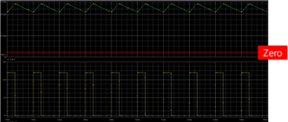
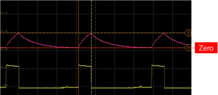
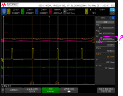
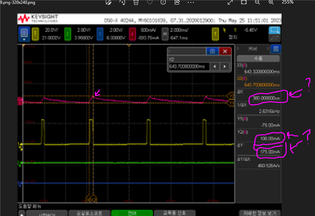
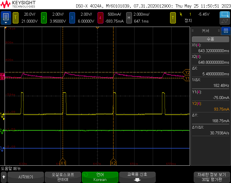
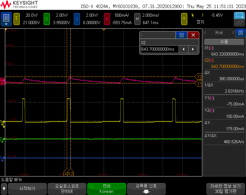
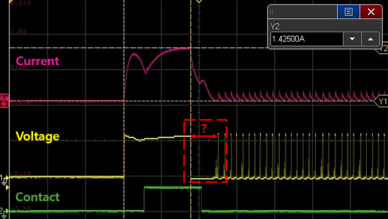
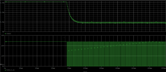
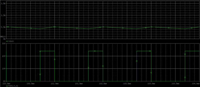
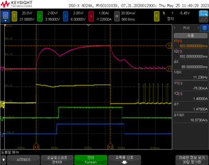
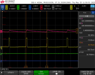
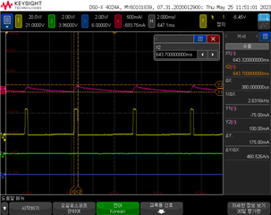
"I designed a circuit using DRV 103 to drive a DC solenoid and conducted tests. However, the PWM frequency is not outputting the desired value, and the solenoid coil current becomes 0 at the moment it turns on. Does the current control always have to be set to 0 for it to reset? Or is there a way to drive PWM regardless of the coil current? Please confirm.

  • ==more information==

    -- expectation value (Simulation Data) 

    -- Test value  -- Current Value is Zero


  • Hello, 

    Could you please provide your schematic? 

    Best Regards, 

    Elizabeth 

  • Hello, 

    This is our schematic

    please check it

    Thanks,

  • Hi Gilho, 

    Based on your surrounding circuitry, we would expect the following typical values: 

    delay time 0.077 s  
    77 ms 
    77000 us 
    duty cycle  1867.049645 at 25kHz 
    oscillator freq 1203.240669 Hz  
    1.203240669

    kHz

    I have also added the calculator I put together to determine these values. 

    1565.DRV103 calculator.xlsx

    Apologies for needing another clarifying question, but it is unclear what is being measured in the plots you've shared. It is additionally difficult to determine the time scale of each of those plots. Could you label the plots and unclip the photo to show the timing per division. 

    What you can do is check whether what you have calculated lines up with what I have in the excel document. 

    Is the issue that the output current draw is 0? For how long is this occurring after start up? 

    Best Regards, 

    Elizabeth

  • Hi, Elizabeth

    The values you mentioned are consistent with what I intended, excluding Duty. I designed the duty to be around 30%.

    I will provide more details about the parameters. This waveform is obtained through simulation. Since the simulation was pefrormed using only simple R and L components, we can ignore the initial transient portion.

    [Total Graph] - 0~200ms

    /resized-image/__size/640x480/__key/communityserver-discussions-components-files/196/_04C8B4CC0CD315D6_.png

    [PWM Graph] - 100~104ms

    /resized-image/__size/640x480/__key/communityserver-discussions-components-files/196/2068.PWM.png

    Cycle : 1ms , Duty : 0.3ms,  Current : 0.4~0.5A

    We want to obtain this data.

    But, Test data is a follows.

    [Total waveform]

    /resized-image/__size/640x240/__key/communityserver-discussions-components-files/196/6862.scope_5F00_67.png

    [PWM waveform-1]

    /resized-image/__size/320x240/__key/communityserver-discussions-components-files/196/5857.scope_5F00_68.png

    [PWM waveform-2]

    /resized-image/__size/320x240/__key/communityserver-discussions-components-files/196/4300.scope_5F00_69.png

    Delay Time :89ms, Cycle :5.48ms(182.48hz), Duty : 0.38ms, Current : 0~0.17A

    Based on the waveform, it appears that the current should reach zero for the cycle to progress.

    Other waveform is same.

    please check it

    Thanks,

  • Hi Gilho, 

    I am looking into this and will have a response for you tomorrow. 

    Best Regards, 

    Elizabeth 

  • Hi Gilho, 

    I believe I understand your question now. I will need your help in identifying the following values as the scopeshots are quite blurry. Or perhaps you could send higher resolution images. 

    My theory is there is a difference in your simulated load and your test board load. It appears your test board completely dissipates the energy, bringing the inductor current to zero before the device is re-enabled while the simulation enables the device while the load is still dissipating the energy. 

    Please see what differences exist between your simulated load and your schematic. 

    Best Regards, 

    Elizabeth 

  • Hi, Elizabeth

    Thank you for your appreciation.

    I have uploaded the requested test waveform again.

    I see that there is a difference between the waveform shown and the simulation waveform, despite using the same load. However, the test was conducted using the DRV-103, while the simulation utilized a simple RL load with PWM source.

    The simulation circuit and the test circuit are as follows

                                                  [Simulation Circuit]                                                                                        [Test Circuit]

    PER - Cycle 

    PW - Duty

    As you understand it, the test board behaves differently from the intended design by completely dissipating the energy until the current reaches zero before the device is reactivated.

    This phenomenon occurs consistently regardless of changing the duty cycle from 30% to 90% or altering the PWM frequency.

    What I understand from your question is whether the DRV-103 requires the inductor current to reach zero for the device to be reactivated.

    Is it necessary for the DRV-103 to reach zero current for the device to activate?

    If not, what other aspects should I verify?

    The solenoid is not being maintained due to the mentioned phenomenon. Although you may be busy, I kindly request your review.

    Thank you. Elizabeth

  • Hello, 

    Thank you for sending those scope shots. It is clear based on those scope shots the device is not setting the frequency we are intending based on the external resistor (f=1203 Hz / 0.8ms period) and instead we are seeing a 5.8ms period/ 172Hz frequency. Can you confirm this is occurring across multiple devices? 

    Unfortunately it is difficult for me to confirm whether the device requires the energy to completely dissipate before turning on due to the age of the device and the intended use case being completely turning on and off the load completely. 

    Could you elaborate on what your intention for this design is? If you are hoping to keep the inductor charged, TI also offers different types of switching regulators which could be more suitable for your application. 

    Best Regards, 

    Elizabeth 

  • Based on my understanding, it seems that the reason for the longer period is because the current needs to reach zero for the device to activate.

    Even with an initial startup current, it can be observed that the current must reach zero before proceeding with PWM.

    The intention of this design is simply to drive a DC solenoid. Initially, a large current is required, so a delay is introduced to maintain it, and once the solenoid is engaged and the plunger contacts the core, a large current is no longer necessary. PWM is used to limit the current value in this case.

    To drive any solenoid, current needs to flow through the coil, and it is necessary to keep the inductor charged. If the energy is dissipated and the device is activated again, the solenoid will return and the maintenance will not be possible.

    To be precise, the current should not drop to zero during PWM control.

    The DRV-103 is also designed for solenoid driving applications and therefore needs to perform these functions.

    Please confirm.

    Thanks, Elizabeth

  • Hello, 

    Thank you for elaborating on your intended use case. 

    Can you confirm this behavior is occurring across multiple devices? 

    Best Regards, 

    Elizabeth