This thread has been locked.

If you have a related question, please click the "Ask a related question" button in the top right corner. The newly created question will be automatically linked to this question.

BQ24271: I2C Bus Collision

Part Number: BQ24271
Other Parts Discussed in Thread: BQ25887, BQ24270, USB2ANY, BQ24160, BQ24765, BQ24250

Hi, 

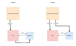
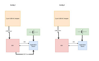
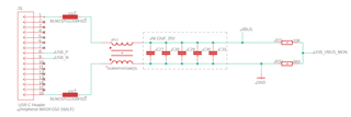
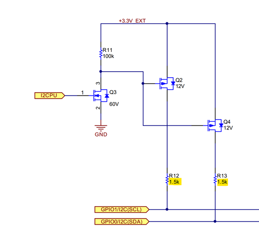
I have an issue with the BQ24271 causing a I2C bus collision. My bus diagram is shown below. 

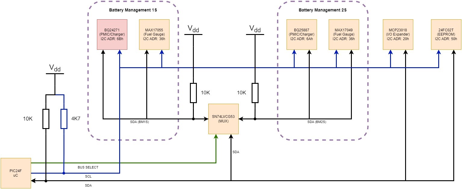
There are 6 devices which sit on the I2C bus running at 100kHz with a PIC uC as the master. There are two battery management sections, which have been split into two busses with a MUX controlling the SDA line due to the fuel gauges sharing the same I2C address. The SPDT MUX was chosen over a specific I2C MUX switching both SCL and SDA due to component availability at the time and cost, with the design intent being that when  the MUX is high-Z on the deselected bus and therefore with the pull-up on SDA, the slave will never receive the start condition.

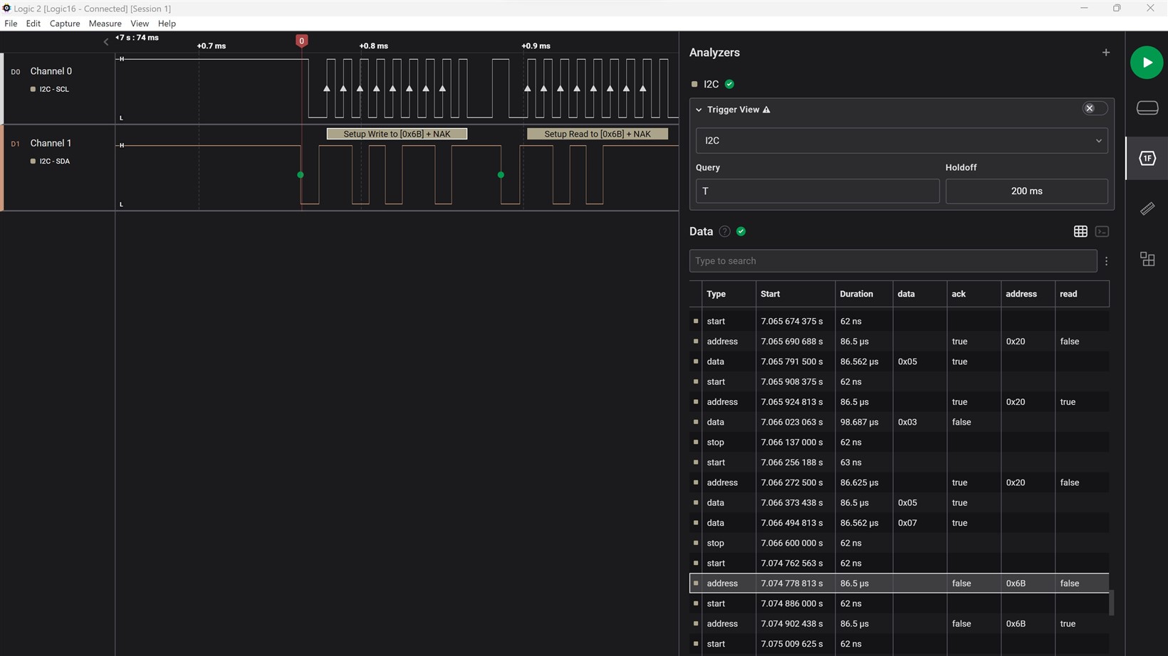
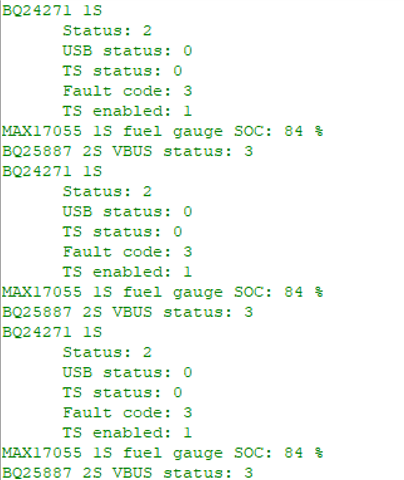
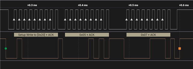
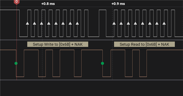
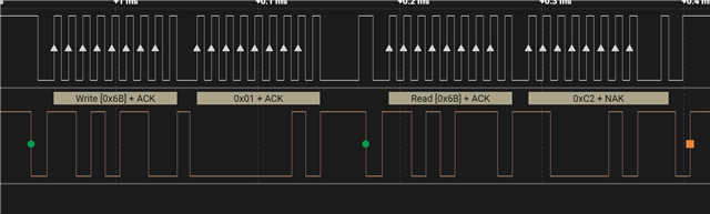
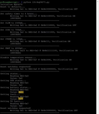
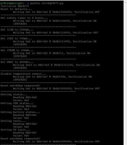
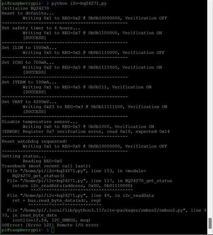
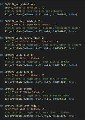
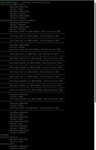
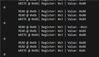
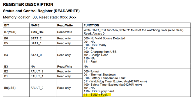
I can read and write to all devices except the BQ24271 reliably, I can also read/write to the MAX17055 on BM1S bus. However, when I write/read to the BQ24271 which shares the BM1S bus, I get a bus collision (mostly, although occasionally not). There are no address conflicts as the remaining devices on the bus are 36h, 20h, & 50h. 

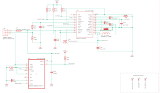
As shown on the diagram I have 4k7 pull up to Vdd on SCL and 10k pull up on both sides of the MUX, thus giving a combined 5K pullup to Vdd on the SDA line. Vdd is 3V.

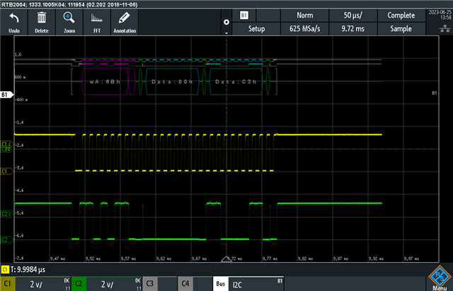
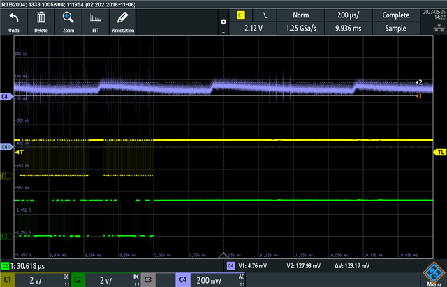
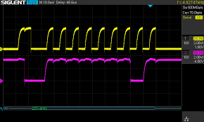
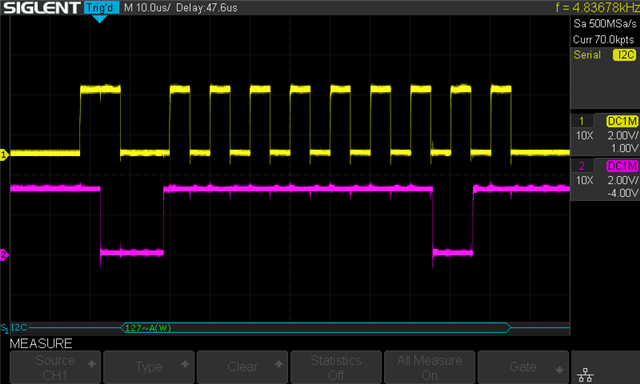
I have looked at the waveforms with an oscilloscope on the bus on both sides of the MUX, there is a nice flat top to all signals, so no alarming effects of parasitic capacitance and the signals look clean.

I get the issue if I keep the bus select static, and I also took the MUX off the board and hard wired SDA to SDA(BM1S), thus making it a single bus without SDA(BM2S) just in case the MUX was doing something strange.

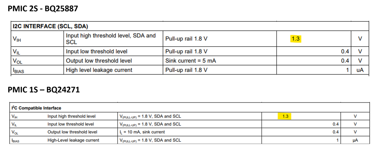
Looking at the DC characteristics between the BQ24271 and the BQ25887, they are the same although the test condition for the sink current differs.

Any help would be most appreciated.


Andy

  • Hi Andy,

    Do you perhaps have the I2C transactions measured in a logic analyzer of some sort and not just an oscilloscope? When these collisions are occurring, are both the BM1S and BM2S powered? I understand that all the addresses are different but it we can narrow it down to just the BQ24271 in some way that'd be good (for example: not powering BM2S). 

    Best Regards,

    Anthony Pham

  • Hi Anthony, thanks for your reply our digital storage oscilloscope provides protocol decoding for I2C, we have a Saleae logic analyser also. I plan to do some more testing in the next day of two. Both BM1S and BM2S are powered and the Vdd is common so there is no possibility that the bus is being pulled down through something not being powered, etc. It's worth noting that I tested without the MUX(removed from the board), linking across SDA to SDA(BM1S) so isolating away from BM2S, with having the same issue. I'll try and get some protocol messages and scope traces and post on here when the bus collision occurs.

  • Hi Andy,

    That sounds like a great start to the debug.

    If you're able to share the saleae files from Logic software when monitor the I2C data lines that would also work. I've worked with the software before so that may work for debug. 

    Looking forward to seeing your results. 

    Best Regards,

    Anthony Pham

  • Hi Anthony,

    I've managed to get a Saleae trace. I will try and capture the physical waveforms at the point of bus collision on our digital storage scope, but it seems the issue of a bus collision occurs with a write.

    These are the write commands, executed in the order:

    BQ24270_set_defaults

    BQ24270_write_ilim

    BQ24270_write_ichg

    BQ24270_write_iterm

    If I read the status or any other register for that matter, then the I2C bus is happy and no bus collisions occur, as soon as I write, or at least most of the time, it causes a bus collision. Incidentally, we use a BQ25887 for the 2S battery management, with no issues, also there is read/write on the EEPROM, Fuel gauge, and  I/O expander, also with no issues. The F/W library we use is the same, in fact it is more of an I2C manager whereby it will queue messages for devices - this library is mature and used in other applications. 

    Here is a link to the saleae capture file: i2c-trace-bus-collision.sal. I placed a marker so you can see what happens when a write occurs after a write on the I/O expander (Adr: 20h)

    Very baffling at the moment, I've never seen anything like this before.

  • Hi Andy,


    I and the team are having trouble with the onedrive link. It seems we're not able to download the file for some reason. I can see your file but the download but doesn't appear to do anything. 


    I'll keep trying but to prevent further delay would you be able to upload them in this tidrive folder I've sent to your email? You should have a link and an access code.

    Best Regards,

    Anthony Pham

  • Hi Anthony, I've now uploaded to TI drive

  • I've also uploaded in the TI drive a complete start-up sequence of all devices which includes writes to configure them, and then just the BQ24271 reading every 1 second which toggles with reading status BQ25887 on the other bus.

  • Hey Andy,

    Appreciate it! I'll take a look at this and the salae data while I get a test setup running. 

    Best Regards,

    Anthony Pham

  • So I've been looking at the Saleae traces myself today. The trace I uploaded to TI drive when a bus collision occurs.

    If I examine a write for slave address 20h which is the I/O expander we get:

    The sequence is as expected, master sends start condition, master sends the address (20h) to the slave, slave ACKs, master sends register 05h, slave ACKs, master sends data 07h, slave ACKs, send stop condition.

    However, for the BQ24271 we get:

    Master sends start condition, master sends the address (6Bh), the slave NAKs!!!

    Not entirely sure why the master then sends another start condition and read, perhaps a bug in the Microchip I2C HAL driver. However why are we getting a NAK for address 6Bh?

    Here is a good read sequence for the BQ24271:

  • Hi Andy,

    Does this happen only on one device? 

    Best Regards,

    Anthony Pham

  • Sadly yes, I've changes the chip 3 times. Same result.

    Can I check that the address is definitely 6Bh. 

  • Hi Andy,

    When you replace the chip, are you moving them onto a different board that doesn't have the I2C bus collisions? I'm curious to see if it's one board you're looking at or if the behavior follows the IC. From what I'm seeing, the salae is correctly using a 7bit address with the corresponding read/write bit. Are you able to try with another I2C master device? 

    Best Regards,

    Anthony Pham. 

  • Hi Anthony,

    We have only one board populated at the moment. However, we have some VQFN24 breakout boards on order, should come tomorrow. So my plan if nothing more than for a sanity check is to place a chip on a breakout board, wire up a minimum hardware requirements, and test on a independent I2C master. 

    I will keep you posted.

  • Hey Andy,

    That would be great, looking forward to the results. It'd definitely be something to better understand the conditions that are needed for the behavior to occur. 

    Best Regards,

    Anthony Pham

  • Hi Anthony, just a quick update. We placed a BQ24271 (one that we took of the application board previously) on a breakout board, wiring up all components so it is as close as possible but bearing in mind we have no control over the layout traces! However, we did wire the grounds in a star configuration. Given we will not need to operate as a battery charger, only query the device over I2C, it achieves the goal. Note we have no battery connected to the breakout board. The BQ24271 is powered via USB (pin 22), and we choose to power from a good quality USB adapter as we wanted to create a real world setup, rather than using an expensive and bench power supply. We then connected it to an independent I2C master (a RasPi, as we had one kicking around) and used external I2C pullups to RasPi power supply pins on the header. We then wrote some python script to send exactly the same commands to the BQ24271 as the PIC. We have noted some interesting behaviour with two different configurations a shown:

    In configuration 1, we were able to perform I2C writes and reads with no errors. However, if we powered the BQ24271 with its own USB power as shown in configuration 2, we got an error from the RasPi master, SMBUS remote IO error 121. We intend to repeat this test and get some signal traces, but this is hints to a ground differential or noise. Note the USB cables were very short (< 40cm) and the grounds are linked. We then added a link from ground on Raspi header to ground on the breakout board, and this appeared to solve the problem, again hinting to a grounding issue.  We thought, OK, this is a crude test, so lets connect the RasPi up to the actual application board (with the PIC) as we have an I2C header we can easily access. Erasing the PIC memory so all I/O is high impedance, and adding a pull-up resistor to the MUX select line to always use battery management 1S. We noticed a similar behaviour, see configurations below:


    In configuration 1, we have the issue where the RasPi reports SMBUS remote IO error 121, we also get the same if we power the application board from the second port on the USB adapter. However, for configuration 2, we allow the application board to be powered from the battery. In this configuration we can perform I2C writes and reads with no errors. 

    I appreciate some traces of the ground, USB VBUS and I2C lines, would be useful and we will post them on here when we re-run the tests in more detail, our objective was to understand the behaviours first and report them.

    For our application board, it is a 4 layer stack with ground and power planes. Here are some circuit snippets FYI. Interestingly the BQ25887 is connected to the same USB VBUS and I2C albeit on the other bus, and the I2C comms works with either battery or USB power.


    The complete Battery management 1S circuit, almost identical to the application reference design.


    And the USB interface with ferrites and CM choke providing USB power for operation and charging.


  • Hi Andy,

    Thanks for coming back with this! This is very thorough and checks off a lot of my questions. It sounds like there is a differential somewhere like you said. Can I confirm though that the BQ24271 does appear to be functional? 

    Best Regards,

    Anthony Pham

  • Hi Anthony,

    In the working scenarios mentioned above, yes. But why the BQ24271 is more sensitive to any other BQ product line we’ve previously used is puzzling. We have not done anything knowingly different. we’ve followed the datasheet to the letter, used recommended layout, etc. We’ve used a number of the BQ series for our customers products and is a “go to” product for us as a design house. 

  • Hi Andy,

    I hear you. I can't say though that I'm able to recreate this problem on my end.

    We then added a link from ground on Raspi header to ground on the breakout board, and this appeared to solve the problem, again hinting to a grounding issue

    I do notice on the schematic that there is a ferrite core from the AGND to the PGND. Has this been tried without the ferrite?

    Best Regards,

    Anthony Pham

  • Hi Anthony,
    Many thanks for your support. Very much appreciated.
    We have a working day planned on this project tomorrow (lots of projects going on!!), so we will get some traces of the failure and working scenarios. We can easily replace the ferrite core with a 0R resistor so we can try this also. But the BQ mounted on a breakout board had no ferrites, a star connected ground. No high currents because there was no load, nor a battery connected, and we got the I2C errors. Unfortunately, the SMBUS library for I2C on Pi which gives the error code 121 is not explicit in what the I2C error is. We might try another library which can give more detailed error info. Also when we connect an oscilloscope with protocol decoder hopefully it'll shine a light on what is happening.

    I can't help thinking we are dark in the wood here and not seeing wood from trees and it feels like we are missing something obvious given you can't simulate this. What I2C master are you testing with and what pull-up values and voltage level? We use I2C amongst many other serial protocols on projects, so we are very comfortable in this area.

    I'll keep you posted.

    BR 

    Andy

  • Hi Andy,

    I'm using the BQ24271 on an EVM board and also with the USB2ANY device. 

    Best Regards,

    Anthony Pham

  • HI Anthony.

    Apologies for the delay. We've been looking at this issue last week and have collected more saleae traces, scope screenshots and also trace data, all of which I would like to share with you. I can't get access to the tidrive to upload them. Can you email me a link please?

    In the meantime, just to give you some feedback we can simulate the same behaviour on both a direct connection(nothing else on the bus) to the BQ24271 which we placed on a breakout board and when connected our application board, driving the I2C bus with a RPi running some python script.

    We have observed that when the battery is at >4.1V, we have reliable I2C comms (on both hardware). We notice that when we connect a USB power adapter we get the following status register values (Note they are bit shifted to represent the contextual value):

    This is indicating a battery fault

    And battery OVP, no idea why and the datasheet does not really elaborate much to possible causes.


    When connected just on battery, we get the following status register values:

    With USB status register reporting VUSB < VUVLO which is what you would expect given it's not connected.

    NOW FOR THE FAILURE!

    As the battery voltage drops to around 4V, that's when all the problems start.
    The BQ24271 I2C becomes unreliable and errors:


    This is 100% repeatable, battery voltage > 4.1 OK, <=4V error for both hardware.

    BUT when the traces don't look too bad:


    I have lots more traces to share.

    So my theory is, there is something going on when the BQ sees a battery voltage that will kick off battery charging. It’s also worth noting at this point that PSEL is pulled high, so max charge current would be 100mA according to the datasheet. VBUS is healthy and has about 120mV ripple:


    There is some crud on VBUS that appears during BQ24271 I2C transmissions.

    It's worth noting that mostly the failure happens when setting device defaults, but sometimes later during the device configuration.

    These are our settings (taken from our Python Script):


    The prototype for the i2c_writeDate is: address, register, data, mask, and verify, which when set will read back and check the value was set correctly.


    Incidentally, the MAX17055 fuel gauge works perfectly on the application board with a battery < 4V.


    We have hit a brick wall as no matter what we try around the BQ24271, no improvements are seen, Could this be a silicone issue? We purchased these devices from DigiKey around 6 weeks ago. 


    We've used many BQ devices in the past, but this particular specimen is causing us major headaches. There is a BQ25887 on the board working fine.

    Our application board has taken a hammering removing and placing various BQ24271 chips, we're getting concerned for how many more times it will tolerate this.


    I look forward to hearing from you. Please do send a link so I can share information.

    BR 

    Andy

  • Hi Andy,

    Thanks again for the investigation. I'll work on getting you a link to be able so that you're able to share. The correlation to battery voltage is very interesting. This is 100% not expected. 

    Would you be able to share your layout when I send you the link for upload?

    Best Regards,

    Anthony Pham

  • Hi Anthony,

    That's great, R.E. Link.

    I can't share the complete schematic or layout without an NDA, but I can share a snippet of the BQ part. I sent a snippet of the schematic earlier in the thread. The only difference was the ferrite bead connecting the AGND, replacing with 0R made no difference, the breakout board hack we made had no ferrites and the behaviour is the same.

    Layer 1(Top):

    Layer 16(Bottom):

    Layer 1&16:

    Layer 2(PWR Plane)

    Layer 15(GND Plane):

    All:


    3D Model of that area of the board

    Top:


    Bottom:


    And for completeness, here is the hack experimental dev board we knocked up on a breakout board. We never intended to use it in charge mode, so not really a thermal plane, but even if it decided to enter that mode, the current is limited to 100mA so should be OK. We also tried to place components somewhat representative to the location on the application board.


    I hope this helps

    BR 

    Andy

  • Hey Andy,

    Thanks for the share. Our team will look it over and I plan to get you in a few days. Appreciate your patience on this. 

    Best Regards,

    Anthony Pham

  • HI Anthony,

    Thanks for organising the link. I've uploaded the data in an archive file (bq24271-test-data.zip) and also our python test scripts for the BQ and the MAX chips. This should run on any Linux box with I2C SMBUS capability with Python >v3.10 we used a RaspPI for our tests.
    We added some annotation on the app-board setup for your information.


    The red square is the BQ24271 circuit highlighted and the red circle is showing a 10k pull up on the BUS select line so the I2C comms is routed to the 1S battery management because the micro is unprogrammed, and would otherwise default to an undermined state. The FPC is the I2C port (glad we put that on there!) which connects to the RaspPi.

    Any questions please feel free to post them, or if you would like us to run a particular test for you and gather data.

    Many thanks for your help.

    BR 

    Andy

  • Hi Anthony,

    Just thought I'd ask if there been any progress?

    BR

    Andy

  • Hey Andy,

    I was able to reserve some lab time today to look at the information you shared. I will see if I can get you an update today.

    Best Regards,

    Anthony Pham

  • Hey Andy,

    We took a look at recreating this phenomenon and discussing why something would work among a star configuration and a delta configuration. This came down to being a ground reference problem. We ended up taking our I2C host (a USB2ANY) and taking it's ground reference and elevating it higher than the BQ24271 GND. 

    At very small increments, we were able to see a very similar behavior where occasionally we would not be able to read but we could write. 

    After each write, I've printed the success value. These are the zero's on the left. For each read, a -0x2C represents a NACK. You can see after we write 0x84, there is a NACK followed by a successful read of 0x84. This happened about when the GND references had a difference of about 300 mV. 

    This so far has been the only way to replicate the successful write then NACK read which I understand is most likely covered in your test with a separate breakout board. 

    As for the battery voltage affects, we've not been able to replicate this. 

    Best Regards,

    Anthony Pham

  • Hi Anthony, this is really interesting, thank you. I will see if I can see a ground difference on both setups, although I’d be surprised on the application board because the grounds are all connected to a huge ground plane on the application board. And of course when running from the micro, that’s connected to the same ground huge plane. Interesting that writes tended to be more problematic than reads for us. What voltage are your pulling the I2C voltage up to on your setup. The pull-ups on our application board setup go to 3V which is effectively the micro supply rail. On the break out board the pull-ups went to the RaspPi 3v3 supply.

    We are getting desperate to resolve this now as we seem to have gotten nowhere ourselves. Even thinking of swapping out the bq with another. A few questions, is there a pin for pin compatible option available? Can we send our breakout board which exhibits the same behaviour as the application board to you for investigation? Could this be a tolerance issue of a batch? Could TI send some samples to us?

    BR

    Andy

  • Hi Andy,

    For a pin-to-pin compatible device, you can take a look at the BQ24160 family of devices. I'll take a look at what the best option might be going forward and get back to you. 

    Best Regards,

    Anthony Pham

  • Hi Anthony, We've tried the BQ24160. Sadly it's suffering the same.
    When the battery is connected and a good voltage >3.9V I2C comms seem to be stable. Below 3.9V or when no battery is connected we get the SDA line being held by the BQ chip. We've tried toggling the SCL line up to 9 cycles, this does release the line, but then as soon as comms is established, it's low again. This is the same on both our application hardware and our breakout board. Also with different I2C hosts.

    I've done a little googling, and stumbled across this article:
    https://e2e.ti.com/support/power-management-group/power-management/f/power-management-forum/162597/i2c-slave---bq24765---battery-charger-hold-data-line-low

    Seems that this chap has the similar issue.

  • Hi Andy,

    Anthony will be back to office Friday and will get back to you when he returns.

    Regards,

    Eric

  • Thank you for letting me know.

    BR

    Andy

  • Hi Andy,

    Are you able to try the other items besides toggling the SCL lines from that thread?

    Best Regards,

    Anthony Pham

  • Hi Anthony,

    Apologies for a little radio silence only we have had to prioritise another project and also with holidays causing delays.

    I'd like to report a little good news.

    Despite using various I2C Master to drive the BQ, we kept experiencing the problem. Just to recap, a bus collision mostly caused when the battery was low or when disconnected which was 100% repeatable.

    So this lead us to look at the USB 2 Any converter you have been using. In the technical spec and indeed looking at the schematic, the I2C pull-ups are a really low value 1.5k. We believe this this is to allow to have may devices on the bus. 


    We have 4k7 on our application board with all other I2C devices happy with that. Historically we have generally used a 4k7 as a general rule of thumb value for 100kB/S bus speed for no more than 5 slaves. For > 5 I2C slaves on a bus, we tend to crunch the numbers and take a lot more scientific approach. On our hack board we used 10k initially and then started to reduce the resistance and observe the results. Much to our surprise, when we got to < 2k5 bus collisions became less as the rising edge of  SCL and SDA became sharper. We then went all in with 1k5 as per USB 2 Any schematic. And wow, we had few bus collisions. Then on the PIC uC there is a setting to disable slew control, this has also improved matters further. 

    So, it seems that the BQ24271 needs really sharp edges on the SCL and SDA. IMHO to have such a relatively low pull-up value of 1k5 is unusual for 100kB/S and a small number of devices. But you live and learn.  I hope this is helpful to other folk who may be having similar issues.

    I won't mark this as resolved yet as we are in the process of testing so we're trying to count chickens before they hatch...

    Andy

  • Hi Andy! 

    Hope your holidays were good! 

    o have such a relatively low pull-up value of 1k5 is unusual for 100kB/S and a small number of devices

    I will note this down for feedback on our end.

    Thanks for keeping me updated and I'll see if I can find some way to help on this on my end. 

    Best Regards,

    Anthony Pham.

  • Hi Anthony,

    So we've been doing a lot of testing today and we can confidently conclude that the issue is now fixed (with a slight software work around) and that the cause is a combination of two issues:

    1. The the SCL ad SDA need rising edges as sharp as possible resembling a near "ideal" square wave, thus pulling the lines up hard. In our tests with no battery connected and 4k7 pull-ups we got consistent failures of many bus collisions when the I2C lines resembled something like this:


    Whilst using a 1k5 pull up presented I2C waveforms like this and vastly reduced bus collisions:


    (N.B. Not our plots, images courtesy of https://www.joshmcguigan.com/blog/internal-pull-up-resistor-i2c/ for illustration)

    2. There is 100% merit in the following post : https://e2e.ti.com/support/power-management-group/power-management/f/power-management-forum/162597/i2c-slave---bq24765---battery-charger-hold-data-line-low and the comment made by Wang5577


    "If the switching is happened during the SDA signal filpping. The ground noise can couple to SMBus clock signal. This noise inserts an extra SMbus clock signal, it may turn a write commend to a Read commend or other devce's address to bq24765 charger address. So, we can see the data line is held low"

    Given that the BQ24271 is a switch mode buck, we believe this is the route cause of why we get this behaviour and with higher value pull-ups, more susceptible.

    Our software work around is to detect the bus-collision, and then assert  up to 9 clocks, by which time the SDA line should become high. However, we have seen an edge case where this did not happen, so as for belt  n braces if this happens we hold SCL low for >35 ms to reset the SDA line as Zachary Glickstein suggested in the post. This then seemed to reset and recovered.

    It's worth mentioning and to put stats, with 4k7 we got a bus collision 1 in around 20 frames, with 1k5 we get a bus collision 1 in around 5,000 frames!

    So we now have one more issue that has came about now that we have reliable I2C communications. When we have a battery connected we get battery fault reported in the status register (value 0x27):


    However, we have no temp sensor fault, all appears to be good on that front. Sadly the datasheet does not go into any reason or cause for what would constitute a battery fault.
    Can you help us on this final hurdle?

    Many thanks.

    BR

    Andy

  • Hey Andy,

    That's good that we've figured out the I2C collisions. 

    Regarding the status register showing 0x27, do you have the value in the Battery and Supply Status Register (0x01)? Are you also able to measure the battery voltage?

    Best Regards,

    Anthony Pham

  • Hi Anthony,

    Thanks for your reply. After many hours staring at the datasheet you would expect I could resight it by now, however after a long day of testing, with your mind steering to look at register 0x01 again, I realised that the we were getting '01-Battery OVP'. The battery voltage is 3.9V, and the Battery Regulation Voltage was at default (3.6V). I hadn't noticed that this had not been set to 4.2V (we commented out that line of code!!!) 
    After setting that, we have a charging status reported on the little hack board (limited to 100mA as there is no thermal plane). We have noticed a lot more bus collisions again, but I expect that is down to the fact its a hack board with poor traces etc. Fingers crossed!

    However, we can now move back to the application board, re-fit a BQ24271, change the pull-ups to 1.5k and apply the other changes and see how we get on.

    Many thanks for you help. It has been very much appreciated. We have certainly learnt more about this particular BQ series than any other we have used! A lot of head scratching and going down rabbit holes along the way, but we got there in the end in understanding some behavioural characteristics. 

    I hope this has been useful to TI and maybe others in the future who stumble upon this thread.

    Once again, many thanks.

    BR

    Andy

  • Hi Anthony,

    Seems that our BQ24270 write issue is still causing problems and come back to haunt us.

    Can you help or puts some explanation/ideas around why when we read any register, all is good,

    But when we write to any register more often than not we get a NAK from the slave? The BQ24270 has a unique address(6Bh) so there are no address conflicts as the remaining devices on the bus are 36h (MAX17055), 20h(I/O Expander), & 50h(EEPROM). 

    Here is a comparison of a write to register 3, the one to the left is good and the one to the write is bad where the BQ gave a NAK after toe write address.

    Notice now we have sharp edges since we decreased the pull ups to 1k5.

    We're wondering if any of these causes for a NAK apply:


    But still very puzzling for why only on a write...

    BR

    Andy

  • Hi Andy,

    That's unfortunate. I'll look into this but curious if you were able to replicate this when just the BQ24271 is connected? 

    Best Regards,

    Anthony Pham

  • Hi Anthony,

    Yes it does only we did not spot it as we were trying to resolve bus collision issue and we only had read commands - never gave it second thought a write command would behave so differently (Never seen this behaviour in all my 20+years using I2C!), It's difficult to quantify the failure rate exactly, we added a counter to count the  good write frames before failure. Its about 1 in 500 to 1000 packets, read never fails. Both cause the occasional bus collision, but we recover from that.

    On the actual hardware, we get a failure 1 in 5(ish), So we started added I2C devices to the bus with the hack board setup, and we saw the failure rate increase as we increased devices up to 5 I2C slaves (All other slaves worked fine). We've tried other I2C masters, same result. We also observed that the write command issue gets worse according to load on the device, when no load it's bad, and improves as the load increases to 100mA, then it gets worse again as the combined battery charge and SYS current heads towards 500mA. However, this is on our hack board setup, so this could be down to traces as they are just wires, etc. We didn't want to spins a PCB and all eval kits were unavailable at the time.  We're absolutely puzzled by this phenomena that it only affects write commands. 

    We have a evaluation kit for the BQ24250 which is not recommended for new designs - hence moving over to the bq24270. We dropped that on the bus on the actual application hardware with the bq2470 removed. And that works like a charm and caused no bus collisions or errors. .

    Being engineers, as much as we want to bottom this problem out, we feel we have done everything we can possibly from isolating from any PCB issues and mux, different I2C masters, different I2C pull ups, adding 220pF capacitance to the bus (makes it worse, as we'd expect). We've reached the end of the road I'm afraid in terms of time effort engineers have given, so we are moving away from the BQ24270, and going to use something else - TBD.

    Without trying a completely different batch of chips, I don't think there is anything else we could have tried or indeed left to try.

    BR 

    Andy

  • Hey Andy,

    I understand the resolve to figure out the root cause. I've been racking my brain as well trying to understand it. Since you are looking to move to a different device, I'll mark your reply and close the thread.

    Greatly appreciate the effort you put into this and the data you collected. 

    Best Regards,

    Anthony Pham