


Other Parts Discussed in Thread: UCC256403
Good day,
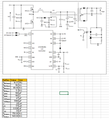
I'm currently working on custom design of LLC DCDC converter with the following specifications: Vout = 13V, Pout = 260W, Vin (min) = 280V, Vin (max) = 440V, frequency (LLC) = 150kHz.
Using the UCC2564x Design Calculator, I get the following results for the schematic:
After completing a first board, the output voltage is as expected but the output keeps shutting down at higher current output. Increasing the voltage input also decreases the output current available. I investigated the signals and here are some of the signals:
350V/14A: Error is detected on RVCC and system goes into fault (CH1 = LO, CH2 = RVCC)
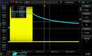
Close-up on LO and RVCC on the left:
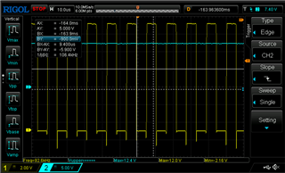
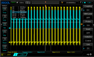
350V/1A (stable 13V output): (CH1 = LO, CH2 = VCR)
Increasing the current output (12A), only increases the occurence of LO switching but it never gets to constant switching: (CH1 = LO, CH2 = VCR)
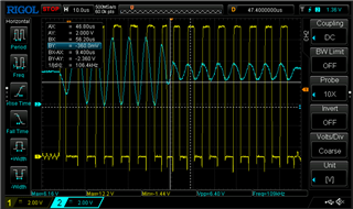
Close up at 350V/2A: (CH1 = LO, CH2 = VCR)
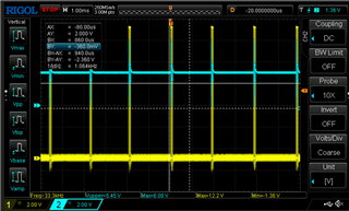
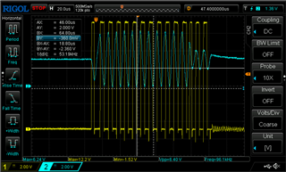
Close up at 350V/6A: (CH1 = LO, CH2 = VCR)
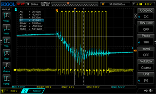
Finally, the output voltage was probed and it doesn't seem to be stable: (CH1 = LO, CH2 = Vout)
Since the frequency of LO doesn't change much (96kHz to 125kHz from 280V to 410V) and the excel calculator shows operating frequency from 94-296kHz, I suspect that there is something wrong with the feedback pin.
Any ideas on what could cause this behaviour on VCR pin and output voltage?
Is the excel calculator appropriate for UCC25630x?
Thanks!
