This thread has been locked.

If you have a related question, please click the "Ask a related question" button in the top right corner. The newly created question will be automatically linked to this question.

UCC2808A-2: VDD supply from TPS2812D

Part Number: UCC2808A-2
Other Parts Discussed in Thread: TPS2812

 Hi,

Can UCC2808A-2D is supplied from LDO in TPS2812D?

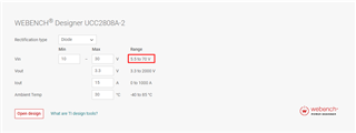
- Input Voltage : typ 24V (10.8V ~ 30V)
- Output Voltage : 48V
- Pout : up to 150W

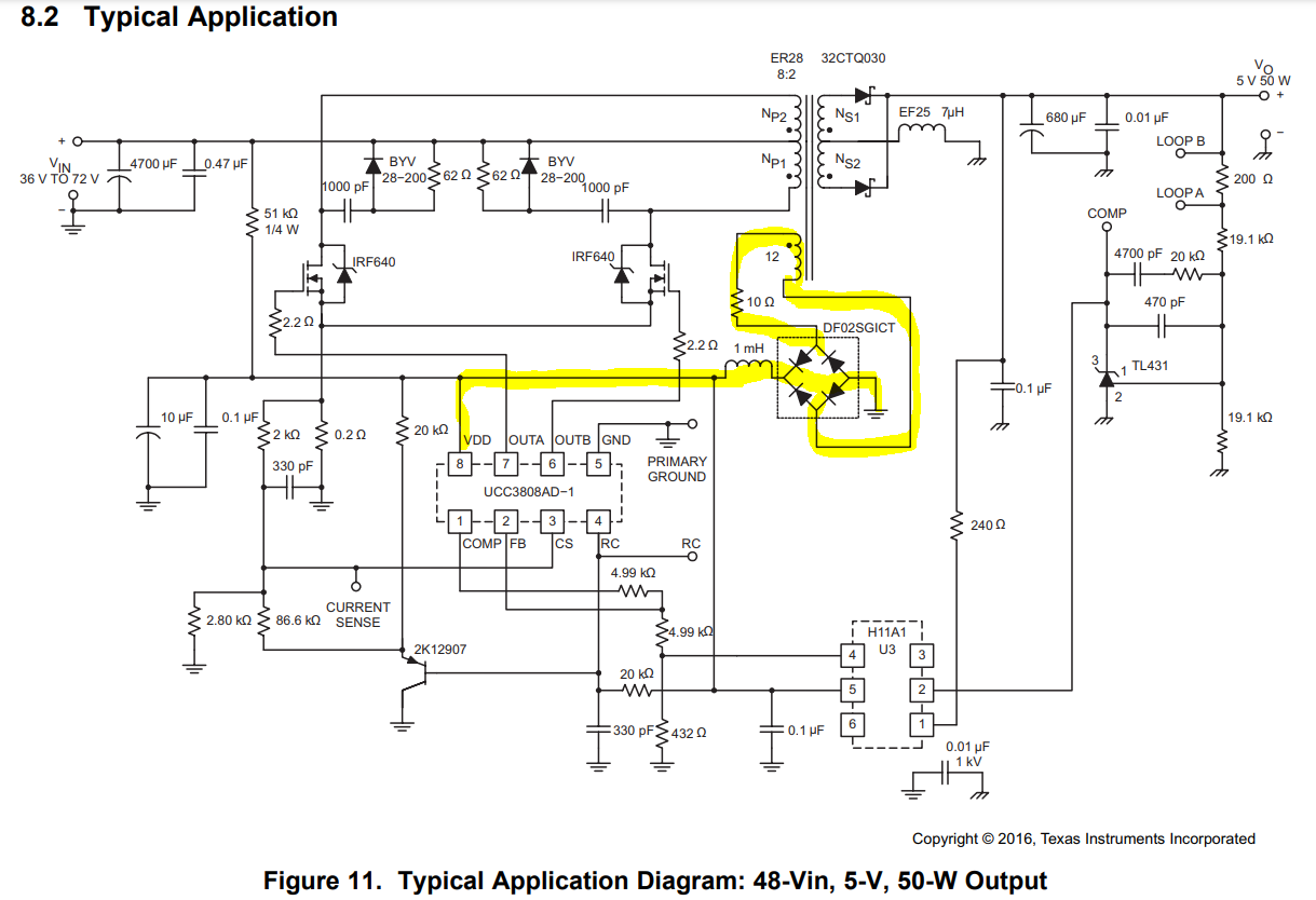
Webench recommended UCC2808A-2D and TPS2812D.

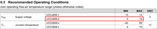
However, input voltage exceeds UCC2808A-2D input range and it needs another supply.

TPS2812D has internal LDO and output is 11.4V.

Can it be used for UCC2808A-2D VDD?

Thanks.

  • Hi David,

    The UCC2808A-2D has a recommended operating voltage range from 5 to 14 volts. The UVLO threshold is 4.5V.

    Why is there a 1V zener diode on the output of the gate driver? This might be inhibiting proper operation.

    I hope this answers your question. 

  • David,

    When the TPS2812 input is ~30V, you are dropping V_LDO=30 V-11.4 V=18.6 V. The UCC2808A-2 requires I_q=2 mA so the TPS2812 is dissipating ~37 mW just due to biasing the UCC2808A-2. You need to calculate the additional power dissipated in the TPS2812 as VCC*ICC + [2*(Qg*VCC*F)] and add this to the 37 mW required by the UCC2808A-2 and make sure you are ok according to below:

    If the power dissipation is too high, I would recommend modifying the transformer to provide a bootstrap winding that could provide bias to the UCC2808A-2 after start-up. This is shown in the application circuit below:

    Regards,

    Steve M

  • Hi Steve

    I want to know exactly what the input voltage range is for the UCC2808A-2

    1. Datasheet Contents

    2. Web page content

    I wonder why the content of the webpage and the datasheet are different.

  • Hi Ki-Yong,

    I will get that Webench bug fixed so it shows the proper range. The datasheet is correct.

    Regards,

    John

  • The Typical Application diagram inserted in the UCC2808A-2 datasheet shows the VIN as 36V to 72V.

    Does the UCC2808A-2 have a Zener diode inside, so it can accept voltages above 14V?

    It's confusing to see different VINs in the same datasheet.

  • Hi Ki-Yong,

    Yes, the zener diode exists. In the above schematic diagram, the 51kOhm 1/4W resistor is limiting the current. into the VDD pin. This is the startup circuit. After the controller is running the aux winding highlighting above supplies the IC. 

    I hope this answers your question.

  • All content below is from the UCCx808A Low-Power Current-Mode Push-Pull PWM datasheet (Rev. F).pdf file. (https://www.ti.com/product/ko-kr/UCC2808A-2)

    I know I've asked this a few times before, but please clarify.

    Why are the input voltage ranges shown in the same Datahsheet different?

    As a result, can I get a 10V to 30V input from the UCC2808A-2?

  • Hi Ki-Yong,

    The datasheet is showing the absolute maximum voltage and current into the VDD pin. I your system expects voltage spikes in excess of 15V, the series resistance needs to limit the current to less than 20mA. The zener clamp inside the IC can not handle much more than that.

    I hope this answers your question.

  • Not the answer I want.

    I think the 36V to 70V in the datasheet means the lowest input voltage is 30V.
    It's not a spikes voltage.

    The IDD shown in the Absolute Maximum Ratings on the datasheet is 10 mA or less.
    Where is the current limit of 20 mA shown?

    Can the UCC2808A-2 accept a 10.8V to 30V input voltage for a typ 24V?
    I want an accurate answer to this question.

  • Hi Ki-Yong,

    The supply current maximum is right below the supply voltage highlighted above. The max 15V was tested at 10mA. The maximum current into the pin shall not exceed 20mA. The typical application in the datasheet has a 51kOhm resistor which limits the current into this pin during startup. Once the controller is running the 10Ohm resistor, 1mH inductor and 10.1uF capacitance is limiting the current and filters the voltage spikes seen on the aux winding. 

    To answer your question. You can not directly connect 24V to VDD. You will need a resistor to help limit the voltage and current into the VDD pin. 

    I hope this answers your question.