Because of the Thanksgiving holiday in the U.S., TI E2E™ design support forum responses may be delayed from November 25 through December 2. Thank you for your patience.

This thread has been locked.

If you have a related question, please click the "Ask a related question" button in the top right corner. The newly created question will be automatically linked to this question.

TPSM365R6: PCB package

Part Number: TPSM365R6

Hi :

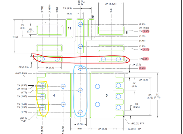
I have some problems about the PCB package for TPSM365R6, please see the below pciture.

1、there are two circles in the Pad 3 and 6 marked in red, it means add two vias into the pad?

2、there are three circles with dotted line in the Pad 4 and 5 marked in yellow, it means add three vias into the pad?

3、there are three circles with dotted line in the Pad 10 marked in light blue, it means add three vias?

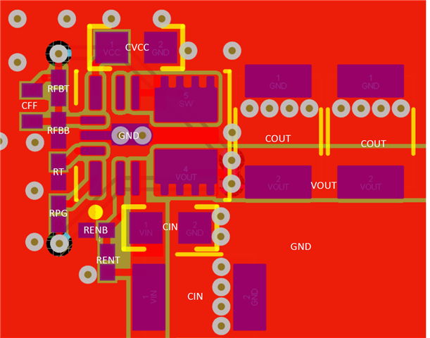
but in the picture for layout example, there are no vias on these pads.

4、the grey lines mean what,especially for pad 10?
I'm looking forwards for your reply.

Thanks and best regards

Kim

  • Hi Kim,

    For your question 1,2,3:  Vias are optional depending on application, refer to device datasheet. If any vias are implemented, refer to their locations shown on this view. It is recommended that vias under paste be filled, plugged or tented.

    For your question 4: Gray refers to another simple drawing of the pad. The final pad size should not exceed the gray line. It is recommended to refer to our EVM PCB package for layout. 

    Hope this can help you, thanks.

    Aurora

  • Hi,

    I will close this thread due to no reply for a long time. If you have other questions in the future, you can ask them again in E2E. Thanks.

    Aurora