This thread has been locked.

If you have a related question, please click the "Ask a related question" button in the top right corner. The newly created question will be automatically linked to this question.

LM5113LLPEVB: Line UVLO and Bootstrap Diode

Part Number: LM5113LLPEVB
Other Parts Discussed in Thread: LM5113, LM5025

Hello,

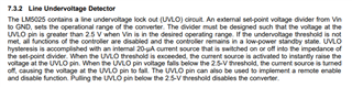
I am currently using the LM5113 Evaluation Board. I would like to know how to calculate the line UVLO thresholds:

a. 13.8V (rising)

b. 10.8V (falling)

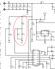
Also, is an external bootstrap diode with a 100 Ohm resistor required to be connected across VDD and HB pins?

Thank you.

Lip San

  • Hi Lip San,

    These values are coming from the LM5025 controller. 

    This voltage divider takes Vin down to exactly 2.5V at 13.8V vin. It achieves hysteresis by activating a 20uA current source, which makes the threshold drop by 20uA * 150k = 3V. Taking 13.8V - 3V = 10.8V. I believe this is how the line voltages are set; I am on the gate driver team not the controllers.

    The bootstrap diode is recommended in the datasheet to avoid startup issues in topologies where HS starts biased high. This topology should not have that issue. As you can see in the block diagrams, the device does have a built-in diode. In this buck topology, you should be okay to leave it out, but should add it if possible. 

    Thanks,

    Alex M.