This thread has been locked.

If you have a related question, please click the "Ask a related question" button in the top right corner. The newly created question will be automatically linked to this question.

TPS61085 Choice of Inductor

Other Parts Discussed in Thread: TPS61085, TPS61086, TPS61087

Hi,

I have a query regarding the choice of inductor.

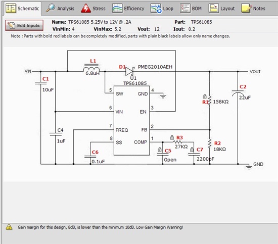
My circuit uses a TPS61085 operating at 650KHZ. Input voltage 4v-5.25v output 12V  20mA -200mA

I initially used an inductor with a saturation current of 0.5A.(Wurth 74451068)

Having discovered Switcher PRO , I upgraded the Inductor to 1.2A Saturation type (Wurth 74455068)

However I found my circuit became very hot, (est 70-80 Deg C) on Diode and TPS61085

Can you explain why this may have occured.

My circuit is showing a low gain warning, would this have something to do with the heating issue?4

Can you explain the significance of a "Gain Margin"

  • Some more information to above:

    I am using a 22uF Tant (0.3R ESR) on the output, which I now know results in a low gain margin

    Is it possible that the first inductor with the low saturation current was limiting the peak currents.

    Therefore,  when the inductor was changed for a part with higher saturation, which did not reduce in inductance at the peak currents, then the low gain margin caused the system to oscillate.

    This would help explain why the device was getting hot, even though the overall current draw from the PSU had not changed.???


  • Hi Joe,


    I do not see any difference between your circuit and the typical application circuit on the datasheet. The only thing that may cause the issue is the output cap that should be ceramic type cap instead.


    I am trying to clarify that as the inductor gets saturated; there will be over shoot in the current that should make the temperature on the part higher. Based on your description, it sounded like for higher inductance, the part gets higher.


    Can you provide some graphs of your Vout, SW, VIN...etc.


    Thanks!

    Tahar

  • Hello Joe,

    I expect that the IC was not able to deliver the requested output voltage and current with the saturated inductor. Nevertheless, measuring the input and output voltages and if possible the inductor current with an oscilloscope is always recommended with a power supply.

    The power dissipation inside the IC with 12V/200mA constand output current will be in the range of 300mW therefore the temperature sounds reasonable. If this temperature increase is too high for your application, I would recommend to use TPS61086 or TPS61087. These devices are similar to TPS61085, but have a thermal pad which helps to remove the power dissipation from the IC and keep the IC cool.

    In addition I recommend to generate a load transient and measure the power supply response to make sure that the converter is stable. For more details, please review this application note: http://www.ti.com/litv/pdf/slva381

    Best regards,
    Brigitte