Hi team,
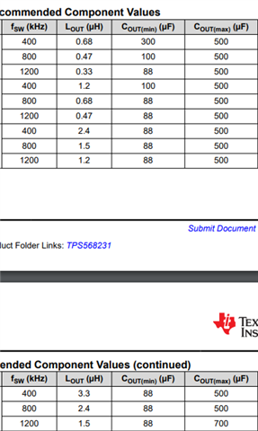
I see LC recommendation is different according to different switching frequency,
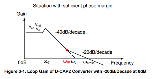
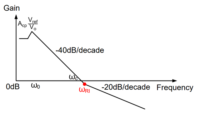
just want to know does internal ripple injection zero change with switching frequency?
if it does, what's the zero table?

This thread has been locked.
If you have a related question, please click the "Ask a related question" button in the top right corner. The newly created question will be automatically linked to this question.
Hi team,
I see LC recommendation is different according to different switching frequency,
just want to know does internal ripple injection zero change with switching frequency?
if it does, what's the zero table?

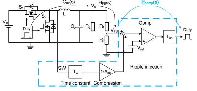
See section 7.3.1 PWM Operation and D-CAP3 Control Mode of the datasheet.
Hi Peter,
does Cout recommendation range base on any equation or purely base on the fact that zero not exceeding crossover frequency?

They are not based on a specific equation. They are recommendations based on empirical measurements and design evaluations from the development of the TPS568231.
Hi Peter,
how about the relationship LC double pole and ripple injection zero,
how far should the zero away from LC pole ? a decade or two?
Please follow the recommended output capacitor ranges provided in the datasheet.
As a general rule with D-CAP3 control, I recommend avoiding setting the L-C resonance double pole lower than 1/2 of the internal zero frequency. Setting the L-C resonance pole less than 1/2 of the internal zero frequency can result in low frequency oscillations in the output voltage during Soft-Start.
Setting the output capacitance lower than the recommended minimum can result in the frequency modulation operating between two frequencies, one lower than the nominal and one higher., resulting in lower efficiency and higher output ripple.
Hi Peter,
about the first one: if we set LC pole too low, you say there will be "low frequency oscillation".
I wonder what's the difference between that oscillation and real oscillation (ex. phase margin=0)

When the LC pole frequency is too low, the loop phase margin can drop near zero before compensation zero increases the phase. This is not classic instability because the loop still has high gain at this low phase point, and the phase rises before the loop gain falls to unity. In this case, the loop is stable under small signal operating conditions, but can become unstable when higher gain is required of the loop at lower frequencies, such as when the output voltage is tracking a moving reference voltage during soft-start.
HI Peter,
I understand , so the loop gain is higher than what it will be when DCap3 converter try to power up.
does this 1/2 rule of thumb has a document or tutorial that we can refer to ?
It comes from experience working with a large number of D-CAP2 and D-CAP3 designs. I am not aware of a specific document on the topic.
got it,
BTW, aside from minimum recommended capacitance,
is there a rule of thumb that you could share regarding we can't set output cap value too small (or LC pole can't be too close to zero)?
ex. like double pole have to be lower than 3/4 of the zero ?
The minimum output capacitance is a factor of the ramp generation time constant, which has not been provided, rather than the internal zero, the inductor value, the feedback divider attenuation, and the switching frequency.
Cout > 2 / ( π * Fsw * Vout/Vref * L / τ )
Without enough capacitance, the output ripple is out of phase with the switching and the switching frequency will not be stable, increasing output ripple voltage.
If a feed-forward capacitor is placed across the high-side feedback resistor, the Vout/Vref factor can be reduced, improving transient response but also increasing the minimum required capacitance.
Hi Peter,
do you know the the Acp of this TPS568231, customer is trying to build a system for our DCAP3 series,
but they can't find Acp value of what they use right now,
would you help provide the Acp of TPS568231 and TPS536211 and TPS563219?


I do not have Tc or Acp immediately available. For the TPS568231, TPS536211, and TPS563219.