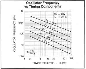
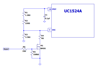
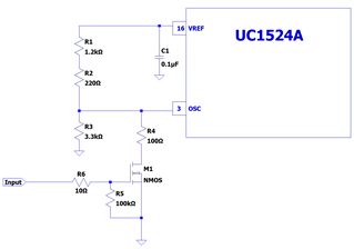
Please tell me the recommended application circuit for OSC.
(The datasheet only mentioned "Sync".)
At that time, please let me know the part numbers of the external parts.

-
Ask a related question
What is a related question?A related question is a question created from another question. When the related question is created, it will be automatically linked to the original question.