This thread has been locked.

If you have a related question, please click the "Ask a related question" button in the top right corner. The newly created question will be automatically linked to this question.

UCC28950: Questions about sync circuit showed in SLUA609

Part Number: UCC28950
Other Parts Discussed in Thread: UCC28050,

Hi to all,

In application report SLUA609 a sync generator circuit example is showed. The goal is to have four different SYNC signals at 200 KHz each.

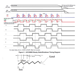
But looking at Figure 10:

Each SYNC signal (VF2 to VF4) has a frequency of 100 KHz (10 us period), so, in my opinion, each of the four UCC28950s will run at 50 KHz.

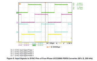
But the application report say that these curves are equivalent to Figure 5 ones, which are 200 KHz each.

What does I am missing?

Thanks.

  • Hello,


    I am reviewing your inquiry and will get back to you shortly.


    Regards,

  • Hello,

    I believe in the UCC28050 that master clock runs at the primary frequency.  So if your switching frequency on the primary is 100 kHz the effective switching of your phase shifted full bridge will be 200 kHz and not 50 kHz.

    Regards,

  • Hi Mike,

    I think that you haven't understood properly my question, sorry.

    The situation described in SLUA609 is the same that I am adopting, four stage interleaved, each stage has an UCC28950 configured as slave.

    In absence of the SYNC signal, primary frequency is set to 100 KHz.  I want to mantain this frequency also with syncronization. So, as indicated in data sheet, SYNC frequency must be 1.8 times greater, e.g. 200 KHz.

    This is well described also in SLUA609, but  when a circuit example to do this is showed, the frequency of every SYNC signal is 100 KHz, that in my opinion is too much low. 

    The question is SYNC frequency vs desidered primary output frequency.

    Thanks!

  • Hello,

    I have synchronized a lot of designs and setting the unsynchronized signal 1/1.8 the sync signal does not sound correct.

    I generally set the unsynchronized oscillator to 80% of the sync frequency.  If I was going to sync to 200 kHz I would set the oscillator frequency to 0.8*200 kHz = 160 kHz.  Not sure why the author of the data sheet chose 1.8. 

    I reviewed application note SLUA609 and you are correct that the sync signals are at 100 kHz.  Each design affective switching is 200 kHz and the primary frequencies are 100 kHz.  So the 100 kHz sync frequency is correct.

    The phase shifted full bridge applies energy to the transformer twice in one primary H Bridge switching period.  This leads to the effective switching frequency to be 2X the primary oscillator.  The following link will bring you to an application note on design the UCC28950 in a PSFB.  I marked figure 4-1 to hopefully explain this better

    https://www.ti.com/lit/an/slua560d/slua560d.pdf

    When the primary switches at 100 kHz the output inductor will see a square wave applied to it of 200 kHz.  This will cause the output inductor ripple current to have a frequency of 200 kHz.

    When it comes to synchronizing a phase shifted full bridge you synchronize the master clock which is half the effective switching frequency.  So a 100 kHz sync frequency on the primary for a 200 kHz design is correct.

    Regards,

  • Hi Mike,

    No doubts about figure 4-1 of SLUA560d. I do know that the output inductor is seeing a frequency that is double with respect to the primary's side.

    But sorry if I still doesn't understand. I have read again the datasheet of UCC28950, the various application notes, and especially SLUA609.

    Apart of the 1.8 or 0.8 factor, the datasheet reported these curves:

    Here I see that:

    • Internal CLK have the same frequency of SYNC_IN signal
    • OUTA and OUTB signals frequency is the half of CLK frequency.

    Again, the datasheet reported also:

    And comparing it with the Figure 4-1 that you have posted too, this is the result:

    In my opinion here is showed that the output inductor frequency is equal to the CLK and SYNC frequency, that they are double with respect to OUTA and OUTB frequency.

    Again, in my opinion, when you set Rt in the UCC28950/1 you are setting the OUTA and OUTB frequency, not the internal CLK frequency.

    SLUA560 seems to confirm this idea in Figure 3:

    So the right SYNC signals seems to be the ones showed in Figure 5:

    That are 200 KHz each.

    Returning to the first question, in my opinion the circuit explained in figure 10 is wrong, because okay it provides 1.25 uS time shifting, but SYNC signals frequency is only 100 KHz:

    What do you think?

    Thank you for your support.

  • Hello,


    I am reviewing your inquiry and will get back to you shortly.


    Regards,

  • Hello,

    If you are using a single inductor in phase shifted full bridge similar to what it is in the following application.  The square wave of voltage applied to it will be 2 X the primary frequency. 

    https://www.ti.com/lit/an/slua560d/slua560d.pdf

    The following link will bring you to the UCC28950 600 W evaluation module (EVM) users guide.  You may want to order one of these and evaluate the performance of the UCC28950 in a phase shifted full bridge.  It should help with your design process.

    https://www.ti.com/lit/pdf/sluub02

    Regards,

  • Hi Mike,

    Sorry, but I don't understand why you aren't replying to my questions. If something about my request is not clear, please tell me. 

    I already have the EVM you suggest, but my question is on syncronization.

    There  are definitely no doubts about that the frequency seeing by the inductor is double with respect to the primary frequency. But from my point of view it is also clear that the primary frequency is the half of the SYNC frequency, see my post above. 

    So - if you confirm this, SLUA560 contains an error on the section where an example of SYNC circuit is explained, and please review it. 

    If not, please explain me your point of view.

    Thank you!

  • Hello,

    I think you are correct on the sync frequency being the same as the affective switching frequency.  In this case the sync frequency should be the same.

    I don't believe that SLUA560 has a section on synchronization.   Can you confirm which applications note you believe has an error in regards to synchronization?

    Regards,

  • Hi Mike,

    Very sorry, I was referring to SLUA609, but I have wrote SLUA560 for mistake. The section that in my opinuion has an error is Section 3- page 10 amd 11. The proposed circuit is generating a SYNC frequency of 100 KHz, that is half of the desidered effective switching frequency.

    Thank you

    Regards

  • Hello,

    Thanks for letting us know.  I will let the TI documentation team now so they can correct it on the next update.

    Regards and Thanks, 

  • Hi Mike,

    Okay, many thanks for your support.

    Best regards