This thread has been locked.

If you have a related question, please click the "Ask a related question" button in the top right corner. The newly created question will be automatically linked to this question.

TPS92691: output rising time and failing time problem

Part Number: TPS92691

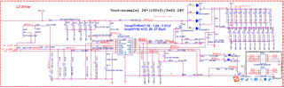
we use TPS92691 to driver laser diode for DLP project, the input voltage is 19.5v and output voltage is 48v and current is 3.0A。

we measured that the rise timing and fail timing of TPS92691's output is out of spec of DLP system requirement。(Rise time:59.6us, spec 20us,  Fall time:65.2us, Spec 20us, our target is lower than 45us )

The circuit design and BOM are the same with attachment circuit。 Can you give me some suggestions for adjustments(Compensation circuit?)? (We tried to remove 4 output capacitors, but the result was useless)

circuit design

  • Hello Alec,

    When you are talking about rise time and fall time I assume you are talking about PWM dimming and the rise and fall time of the current is longer than what you expect.  If that is the case than you need to reduce the DR12 and DR15 values.  In your specification we do not have these resistors or the DR12 and DR15.

    Thanks Tuan

  • Yes, The rise time and falling time refer to the time required for the current to rise from 0A to 3A. We found that adjusting the resistance(DR14) can reduced this time(Rise time:59.6us->35.77us    Fall time:65.2us->36.58us ). Will such adjustments affect the stability of the chip's operation?  What measurements do we need to confirm?

  • Hello Alec,

    No it will not affect the stability.  As I mentioned, if you look in our data sheet we do not have the resistors or diodes that was use to slow down the rise or fall times.  Note that using those components to slow down the rise or fall times will not be accurate with different FET's being used since the FET's can have different gate capacitance/charge.

    Thanks Tuan

  • Hi Tuan, 

    I replaced DR12,DR15,DD3,DD4 with 0 ohm resistor. It seems that the solution to this problem is not helpful. We adjust the voltage of IADJ pin to dynamically adjust the output current(voltage). Is high load the main cause of this problem? limitation?

  • Hi Alec,

    i thought you were using the PWM input to ramp up/down the current and that’s why I recommended that.  if you are using IADJ to ramp up and down the out put current then there is not much you can do with the existing design without incurring other issues because this related to the power stage design.  

    Thanks Tuan