This thread has been locked.

If you have a related question, please click the "Ask a related question" button in the top right corner. The newly created question will be automatically linked to this question.

TPS54331: Device cannot start up under 5V input

Part Number: TPS54331

Hi team,

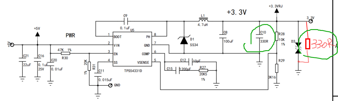
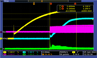
My customer is using TPS54331 as 5V to 3.3V converter. The device would be start up at a 330R fake load and real load would be added ~5s after device power up.

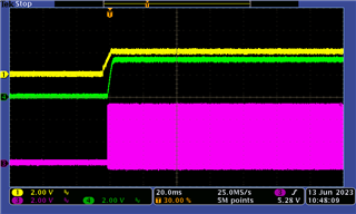
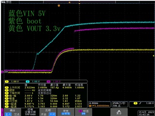
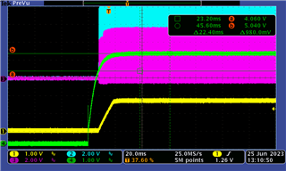
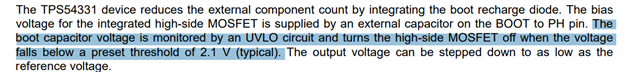
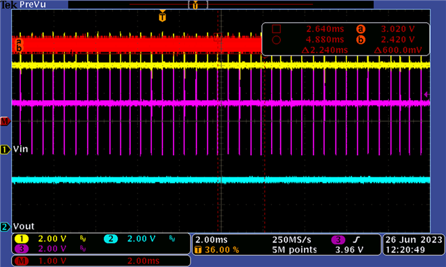
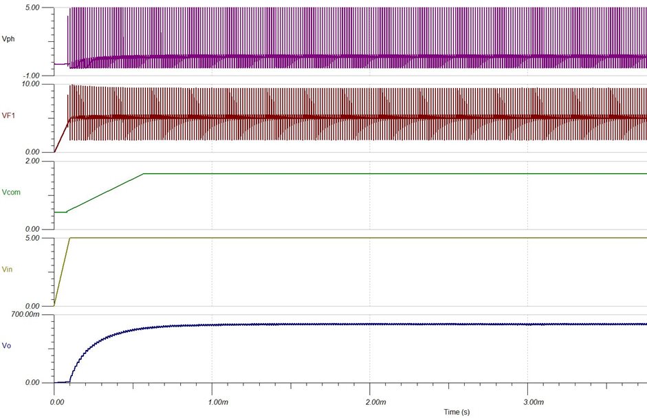
They found there is a possibility that the device cannot start up sucessfully. I did some simulation and the result seems the same. The COMP voltage is clamped at ~1.6V, and converter is working under a 'cycle by cycle HICCUP mode'.

Could you kindly check if there is any special consideration for this device to work under a 5V to 3.3V scenario? Thanks!

slim041a.tsc

Regards,

Brian

  • Hi Brian,

    I tested 54331EVM board with default 3.3Vout, didn't find problems of 5Vin startup.

    Condition: 5Vin-3.3Vout-10ohm load-EN turned on

    (Yellow: EN; Green: Vout; Pink: SW)

    Could you share customer schematic and their issue waveforms? Thanks.

  • Hi Miranda,

    Thanks for your kindly reply.

    Schematic:

    Vout:

    SW Waveform( PH ):

    It seems the converting is not switching.

    Regards,

    Brian

  • Hi Brian,

    To narrow down the issue, would you please check below items?

    1. Check whether device damaged, do ABA test. Also check the failure rate.

    2. Sweeping the Vin, check whether higher Vin like 12Vin can start up normally.

    3. Capture the SW/Vout/Vin/IL waveforms during startup and steady state, check whether there's any abnormality.

  • Hi Miranda,

    I suggested the customer to do more test, and here are more updates.

    First l suggested customer to measure the start up waveform for VIN BOOT VOUT and PH. Customer measured in 2 separate pictures due to probe limitation.

    We found:

    1) Vout, VPH and boot started to rise even before VIN reached the configured start-up point.

    2) Vboot suddenly rised up when input reached ~4.6.

    I cannot understand why we are seeing a rising vout even when the converter should be in UVLO. 

    Thanks,

    Brian

  • Hi Brian,

    I will check it both in simulation and EVM tomorrow.

    Could you please share the failure rate of TPS54331 in customer? And is C8 electrolytic capacitor? What is the value of real load that is connected after 5s?

    BRs

    Zixu

  • Hi Brian,

    I have modified EVM based on customer schematic, finding no phenomenon shown in this thread. The startup process looks good

    The simulation shows similar result, revealing no issue in startup. Could you please help to share layout of customer? 

    And could you please help to conduct actions from Miranda?

    BRs

    Zixu

  • Hi Brian,

    1. I looked through your waveforms. Weirdly there's no pulse on PH/Boot pin during startup. Per Jerry said, we couldn't reproduce the issue on EVM board. Below is the EVM waveform using customer BOM (4.7uH, 1*100uF Cout).

    (Blue: Boot-pin; Pink: PH-pin; Green: Vin-pin; Yellow: SS-pin)

    To avoid measurement error, could you let customers compare bad board VS good board waveforms in their bench?

    2. About your question, are you asking why they set EN UVLO Vstart to ~4.14V (according to datasheet 7.3.4), but actually they measured ~3Vin Vstart? I use same EN resistors on EVM, the Vstart value is close to 4.14V.

    Would you please check the EN resistors values in customer board? Maybe they didn't install EN resistors, device EN-pin has internal pull-up, then the Vin UVLO threshold will be 3.5V (max).

  • Hi Brian,

    I did more tests, seems your issue is caused by device BOOT_UV protection.

    The boot capacitor is to power high-side FET driving circuit. When high-side FET on-time is long (e.g. lower Vin, higher Vout), the boot cap may be discharged to below 2.1V threshold, the device will trigger BOOT_UV protection. You will see the device stop switching, Vout will drop.


    You could capture BOOT&SW waveforms and do subtraction, then you will get boot cap voltage, please check whether triggered 2.1V threshold.

    Below is the example waveforms I tested on 54331 EVM board.

    • 5Vin-3.3Vout-0A ------- didn’t trigger BOOT_UV

                (Yellow: BOOT; Pink: SW(PH); Blue: Vout; Red: BOOT-SW)


    • 4.6Vin-3.3Vout-0A ------ trigger BOOT_UV

              (Yellow: BOOT; Pink: SW(PH); Blue: Vout; Red: BOOT-SW)


    Below methods may help to avoid BOOT_UV at no load. Please try in your side.

    • Add dummy resistor at output (did they install 330ohm? please install), to increase Iout at no load;
    • Maybe boot cap (C9) effective value is much smaller than rated 0.1uF, please use X7R- or X5R-grade, or use larger capacitance like 0.22uF.