Other Parts Discussed in Thread: , BQ25125, BQ25798
I am using the BQ25120YFPT in a custom circuit design, the schematic is included as an attachment. The device is a smart wearable that accepts tactile input from the user, which then broadcasts a message over BLE to a smartphone, receives a BLE confirmation message, provides haptic feedback (vibration motor M1), and then goes back to sleep. The main BLE SoC is Silicon Labs BGM220SC22WGA2, the BQ25120YFPT is used for regulating coin cell (BT1) battery voltage to system Vcc (1.8V) used to power the BLE SoC. It is also used to charge the coin cell from input charge contacts. I also connected the vibration motor to the BQ25120YFPT as a load on LS/LDO.
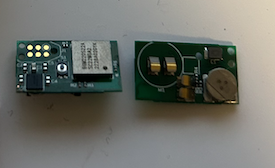
I got the custom board fabricated (x10), I've included the gerbers and BOM if it helps. On most of the boards the battery voltage is below 2V and I am not getting anything on Vcc. When I connect Vin to 4V from a power supply I still get nothing out and the battery does not charge. I assume that I did not design the circuit correctly for using the BQ25120YFPT with these other components, for instance I connected the I2C, RESET and LSCTRL lines to the Si Labs SoC for control, but this SoC is powered by the system out so I'm not sure if that is correct.
Could you please take a look at the schematic and see if there is anything wrong with the circuit around part U2? If I removed the I2C pullup resistors and/or cut some traces would I be able to get this board to to start charging the battery and bringing Vcc to 1.8V to power the MCU?
Please let me know if I can provide more details. Also please do not circulate attached documents as they are confidential and contain proprietary information.
Thanks!
Lance