This thread has been locked.

If you have a related question, please click the "Ask a related question" button in the top right corner. The newly created question will be automatically linked to this question.

LM7480-Q1: Mosfet Fails in Pulse Test (Jumpstart)

Part Number: LM7480-Q1

Hello,

The mosfet is broken in the jumpstart test, how can we solve this problem?

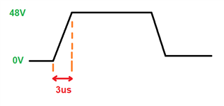
In the jumpstart test, the voltage goes from 0V to 48V in 3us and stays there for 1 minute. As a result of the test, the mosfet (Q1) remains as a short circuit, and after a while the OVP is broken.

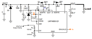
I created a similar schematic of the product I designed, below.


What should we do both to pass this test and to pass the 7637-2 pulse tests that we will enter in the future, thank you in advance for your support.

  • Q1 transistor part number: BUK6D385-100EX

  • Hi Omer,

    The schematic looks good to me. I do not see any reason why a 100V FET would be damaged when 48V is applied at its input. 

    Can you share waveforms with the below signals captured during startup and shutdown

    • Vin, Vout, Iin (input current), HGATE
  • Hello, unfortunately I do not have the opportunity and time to do this right now and I need to find a solution in a short time.

    My first prediction is that the inrush current is burning the mosfet. When I reduced the output capacity by 100uF, I saw that the mosfet did not deteriorate.

    but I need to use that 100uF at the output and I would be glad if you could help me solve it this way without changing the layout.

  • Hi Omer,

    If this is a MOSFET SOA issue during startup, you will have to increase the Cdvdt capacitance from 10nF to higher value. This will increase the turn ON time of the FET. I can provide you the Cdvdt value to maintain the FET operation within its SOA if you can provide the below details,

    • Max Vin:
    • Total Output capacitance:
    • Max Ambient Temperature:
    • Load Current during startup:
    • Load turn ON threshold:
    • Max Vin: jumpstart:48V and this product will then enter all pulse tests in 7637-2, there are 200V pulses.
    • Total Output capacitance: 109uF
    • Max Ambient Temperature: 80°C
    • Load Current during startup: The product is 100mA at rated operation (I may not have understood this question correctly)
    • Load turn ON threshold: ICs in the product start to work after 6V, but for stable operation, min. 16V is the healthiest

    Thank you very much for your quick turnaround and guidance.

  • Hi Omer,

    The BUK6D385-100EX FET does not have decent SOA and is not suitable for operating in saturation region. 

    I have tried calculating the Cdvdt required to get good SOA margin during startup at 48V with 100uF capacitor  but could not get any SOA margin even for higher Cdvdt capacitors. 

    The only solution here is to replace the BUK6D385-100EX FET with another FET which has  better SOA. 

  • I increased the 10nf to 100nF in the snubber circuit connected to the HGATE (at 25°C ambient temperature). the mosfet is not broken. If the product continues to work in this way, will we have problems in the future?
    My new concern now is will we have trouble with the 7637-2 pulse 3b test? (TVs diode at the input clamps at 77Volta)

  • Hi Omer,

    Our calculations for FET SOA include calculations at Max Ambient temperature and  FET SOA derating for temperature. So, you may see the FET may not fail at 25C operation but it can fail at higher temperatures.

    ISO 7637-2 Pulse 3B is a very fast repetitive pulse of 100's of ns that is usually absorbed by the input and output ceramic capacitors. What is the TVS used at the input ?

  • Hello,

    I will work on FET SOA in more detail, thank you for the information you shared. I have one more request, can you suggest a suitable mosfet for my design or especially which parameter should be?

    TVS PN: TPSMD48A

    Thanks a lot for your answers

  • Hi Omer,

    Unfortunately I will not  be able to suggest a Mosfet but you can refer to datasheet section '10.3.2.5 MOSFET Q1 Selection' for Mosfet selection guidelines.

    I can also share an excel based design calculator (by early next week) which calculates the SOA margin for a given system parameters. 

  • Thank you very much for your support.
    Thank you also in the calculator, I'll be looking forward to it

  • Hi Omer,

    Please find attached FET inrush SOA margin calculator that you can use. Please go through the videos provided in the links to understand how to use/enter the values in the design calculator.

     INRUSH_FET_SOA Margin Calculator.XLSX 

  • Thanks for all your support, I'm so lucky to have come across you