This thread has been locked.

If you have a related question, please click the "Ask a related question" button in the top right corner. The newly created question will be automatically linked to this question.

LMR51420: Solving equations doesn't match datasheet values

Part Number: LMR51420

Hello! I am trying to use the equations in section 9.2.2 in the LMR51420 datasheet to solve for inductor and capacitor selections. However, using the example design targets in table 9-3 does not give me the same values given throughout section 9.2.2. I've triple checked the equations I wrote in excel and they appear to match the datasheet. Maybe I'm understanding them wrong? See attached excel document.LMR51420_ComponentSelection.xlsx

Inputs & Outputs

Cells A3 - J3 contain inputs that match table 9-3 in the datasheet.

Row 6 and 7 contain inputs that can be copy/pasted into cells A3 - J3. Row 7 matches the datasheet. Row 6 contains the target numbers for my application.

Cells A12 - G12 contain constants that are either fixed in the datasheet (like switching frequency) or intermediate constants like those described at the end of section 9.2.2.5.

Cells A17 - E17 are the primary outputs we care about: R_FBB, minimum inductance, maximum ESR, minimum C_out.

Equations that work

Equation 9: R_FBT and R_FBB are solved in cell H3 and A16 and matches the values shown in 9.2.2.2.

Equation 14: C_OUT-minimum is solved for in cell E17 and matches the 32μF value in datasheet section 9.2.2.5.

Equations that I'm uncertain are working

Equation 10: Δi_L is solved in B12 but there is no reference value in the datasheet to know if this is correct. Is this supposed to be the RMS current referenced in 9.2.2.4? If so then it should be 3 A but I am getting 0.6 A.

Equations that aren't working

Equation 11: Minimum inductance is solved for in cell B17. It does not match the datasheet value of 9.7μH, it shows 14μH. I'm off by 44%.

Equation 12: Maximum ESR is solved for in cell C17. 9.2.2.5 says this should compute to 75mΩ but I am getting 41 mΩ. I'm off by 54%.

Equation 13: C_OUT-minimum is solved in D17. 9.2.2.5 says this should compute to 12μF but I am getting 6 μF. I'm off by 50%.

Questions

Ultimately I'm just wondering "What am I doing wrong?". My guess is I am not understanding some of the units correctly in the constants listed in cells A12 - G12. WEBENCH has this part number listed and solves for C_OUT and L values close to the datasheet but are still a little off compared to the datasheet example.

Any help would be appreciated, thanks!

  • Hello

    I will assign this to the application engineer that worked on this device.

    Thanks

  • Hi Michael

    I have checked the excel you attached, your calculation is correct.

    For the different values:

    1. We normally select the inductor value based on the VIN_norminal, the 9.7uH value should be yielded by replacing 12V in the equation.

    And this does mean that the K_IND is not exactly 0.3 at the VIN_max, but the range of  0.2-0.4 for K_IND would be OK.

    2. Your calculation for The ESR value and the C_OUT_min value are also correct(your G3 is 0.5% and Vo_ripple is 25mV though). There might be some typo or linked-to-wrong-value here. We will change this if we do the datasheet update.

    3. For the Δi_L , this is ripple current of the iL, and your calculation is also right.

    Thanks and best regards

  • Hi Gui,

    Thanks for the response!

    1. I see that changing the voltage value to 12 V in cell B3 does indeed change the inductor L_min to 9.7 μH which matches the datasheet value. This should be noted in the datasheet as this is not obvious in my opinion.

    2. C_ESR (cell C17) does not match the 75mΩ in the datasheet unless I set the ripple percentage to 0.9% (cell G3) which results in a ripple voltage of 45mV (cell F12). Table 9-3 uses an example ripple percentage of 0.5% which results in a ripple of 25 mV, section 9.2.2.5 then overrides this to 30 mV for some unknown reason. If I'm right, why is the datasheet wrong? Are you sure I am right?

    3. C_OUT_min (cell D17) does not match the datasheet value of 12 μF unless I set the ripple percentage to 0.25% which results in a ripple voltage of 12.5 mV. Again, if I'm right, why is the datasheet wrong? Are you sure I am right?

    4. If my Δi_L equation is right, and I'm seeing a 0.6 A ripple, then why does the datasheet say that we need 3A RMS and 4 A peak capable inductor?

    Let me know, thanks!

  • Hi Michael

    I checked the calculate equation you typed in your excel and did the calculation from my side also, that's why I think you didn't make wrong about the calculation.

    As for the datasheet , the equation is correct, but yes as you said the specific value in the statement does have some in conformity. Both the C_ESR and the C_OUT_min section. Yes we are about to update this when we do the datasheet refreshment.

    We suggest choosing inductor that has saturation current that larger than the peak current of the device(3.5A peak value in the datasheet), in case when the 'vout short to ground' status happen.

    Thanks and best regards.

  • Hi Gui,

    1. Matching the inductor current capability to the short circuit condition makes sense and I see that the "High-side peak current limit" is 3.5 A typical. I was forgetting that Δi_L is just ripple and not the peak current.

    2. It's a bummer that the equations do not match the datasheet examples as this does not instill confidence in the part. The datasheet example value is double the value that the equations give (12uF vs 6uF). If I double the C_OUT_min capacitor for a safety factor is this OK?

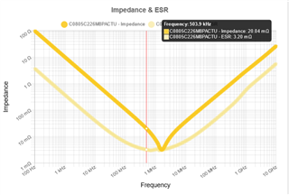
    3. Is the ESR calculated for C_OUT_ESR a maximum ESR? What frequency is this supposed to be calculated for, the switching frequency of 500 kHz? The image below shows Kemets Ksim tool for a capacitor at 500 kHz (click it so that it's not blurry).

    4. How do I use section 8.3.4 to determine the minimum switching frequency that the device might use in PFM mode in light loads to make sure that my C_OUT_ESR is still within spec?

  • Hi Michael

    Yes, Doule the C_OUT_min capacitor for a safety factor is this OK;

    It's maximum ESR. Yes the 500kHz switching frequency should be used(use 1.1MHz when you choose LMR51420Y);

    During light-load operation/PFM mode, you can estimate the fsw by the equation 1/2*L*ipk2*fsw=Po=Vo*Io

    And for the vout ripple, It's more related to the Cout value other than the ESR.

    The inductor current upslope is (VIN-VOUT)/L, the downslope is VOUT/L.  I_PFM-pk=0.3A as stated in the datasheet.

    The resulting t_on is (L * I_PFM-pk) / (VIN-VOUT).

    The t_off is  (L * I_PFM-pk) / (VOUT)

    The total charge to the capacitor in PFM is estimated by Q_PFM= (0.5) * (t_on+t_off) * I_PFM-pk.

    The VOUT ripple will be Q_PFM / COUT.

    Ultimately to reduce the output ripple in PFM you will have to increase the output capacitance or reduce the peak current.

    Thanks and best regards

  • Awesome, this helps so much! I used this to narrow down my real-world components and I'm playing with the psice sims to verify them. Please leave this thread open for a few days while I verify. Thanks!

  • Hi Michael

    Yes. You can reply here when you got your further questions.

    Thank you.

  • Hi Gui,

    I was able to verify the capacitor and inductor selection with the pspice for TI tool. Thank you! Appreciate your help on this issue :)