Other Parts Discussed in Thread: LMR36520, OPA454
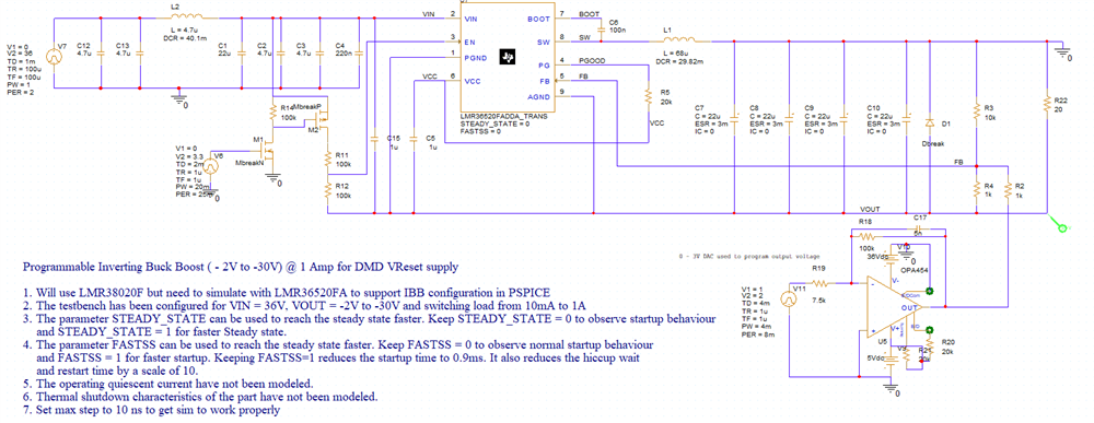
I have an application where I need a programmable inverting buck boost converter. Inputs available are +/-36V, +5V, Programmable Output need to be roughly = -2V to -32V @ 1 Amp. After searching the internet and reading several white papers I put together an inverting buck boost circuit using PSPICE for TI and used a LMR36520 even though I will need to use a LMR38020 or equivalent for my final design. I choose the LMR36520 for the simulation since the Grounds are separated in the PSPICE model and it can be used to simulate an inverting buck boost. In my circuit I will use a 2.5 V DAC to feed a high voltage op-amp that can generate a large negative bias voltage to modify the feedback of the inverting buck boost.
I thought about just using several of the high voltage op-amps powered with +/-36V and fed with a DAC to generate the programmable voltage, but it is way to inefficient for my application with a tremendous amount of waste heat. (When output = -2 there would be a (36-2) * 1 Amp = 34 Watts of waste heat!)
I have done many simulations of the op-amp controlled IBB circuit and it is working well. However before I commit to this design I wanted to run it past the Power Management experts to see if there is a better way to do this or if there might be some issues with this circuit. I have to level shift the EN control signal and I put that into the simulation also. I have used the formulas for IBB to calculate inductor value and ripple current, etc. By changing the DAC voltage from 0 to 2.5 volts I can make the output of the IBB go from roughly -2Volts to -32Volts which is what I need for my application. In the circuit below the pulse generator connected to the op-amp represents the 2.5V DAC. The OPA454 is powered with +5/-36V since those are available in the system I'm using. The op-amp is configured in an inverting configuration so that a 0 - 2.5 volt DAC voltage will create a negative voltage that allows the output voltage to be controlled. My system will have a way to feed back the voltage through a ADC so that the Sitara processor controlling everything will be able to calibrate this negative voltage and check for over current conditions.