This thread has been locked.

If you have a related question, please click the "Ask a related question" button in the top right corner. The newly created question will be automatically linked to this question.

LM5026: Clamp Capacitor Current

Part Number: LM5026

Hi,

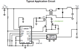
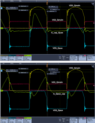
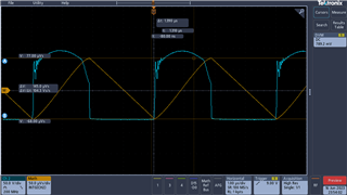
We are optimizing our low side active clamp forward converter with synchronous rectifier and the following figure shows the VDS_Qmain (Ch1), VGS_Qaux (Ch2), VGS_Qmain (Ch3) and the current from clamp capacitor to Qaux (Ch4). I tried different delay durations but there is a strange constant current flowing from Qaux to Cclamp when VDS_Qmain = 0 V. Is there any reason specific for this topology?

Cclamp = 20 nF and Fsw = 250 KHz.

  • Hi,

    Which part of the current do you think not normal? Where did you measure the current? You can label it in the below figure and also label the current you think not normal.  

  • So indicated I_meas should be zero where the VDS_Qmain is zero, but I measure about 100 mA constant current.

  • Suheyl,

    I see the CH4, ICLAMP_CAP_QAUX is showing a DC offset in the clamp capacitor current waveform. 

    1. Please make sure to disconnect the current probe from the circuit, lock the jaw and auto zero/degauss the probe. Verify there is zero offset in the probe waveform before connecting into the circuit.
    2. When the main MOSFET, Q_MAIN, is conducting, the clamp capacitor is connected to GND and appears as parallel to Q_AUX. Can you please show the VDS of QAUX on CH2?
    3. From your VDS_QMAIN waveform, it appears your clamp capacitor value may be large. When the clamp capacitor value is properly sized, you should see about 10-20% ripple on VDS, appearing as a "rounded top" on the VDS waveform. Your VDS_QMAIN waveform looks very flat across the top. Try reducing the clamp capacitor value.

    Regards,

    Steve

  • Hi Suheyl,

    You can verify if the current if it is real by probing Vds of Qaux to see how much this voltage is. Based on your current direction, the current flowing opposite direction. Since Qmain is on, the nearest loop would be clamping capacitor, Qmain drain to source, then to GND then flowing Qaux. But Qaux should be off. If your current probe is ok, then Qaux is not off.

  • Hi,

    I reduced the clamp capacitor as suggested which lead to better overall results. Below are two measurements with current probe with zero offset adjustments but measuring in opposite directions and it shows same negative offset in both. I think it indicates that there is something wrong with the current probe, am I right?  

    Regards, 

  • Suheyl,

    Your DC offset was previously ~100mA but now looks to be reduced to ~20mA. You could measure the AC voltage across the transformer primary and confirms the volt-second balance is equal. Even if you do not pursue this, I think the waveforms look correct and maybe your current probe/amplifier is the culprit?

    Regards,

    Steve

  • Steven,

    I measured volt-second across primary winding and there is about 10% difference. Maybe this is coming from the ringing present in the waveform, despite the fact that I put some RC snubbers. Is this volt-second unbalance acceptable? Still I will try to reduce ringing and voltage overshoot on secondary side. 

    Best regards.

    Suheyl