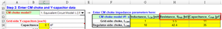
In TPSF12Cx quickstart calculator Rev A2.xlsm, what's the definition of RPAR and CPAR in CM choke model. Could you draw the equivalent model to let me know the location of RPAR and CPAR?

-
Ask a related question
What is a related question?A related question is a question created from another question. When the related question is created, it will be automatically linked to the original question.