This thread has been locked.

If you have a related question, please click the "Ask a related question" button in the top right corner. The newly created question will be automatically linked to this question.

BQ76952: Poorly working sleep mode

Part Number: BQ76952

Hi Experts,

Good day

We use BQ76952 in our BMS. It is a protection electronics for LiIon battery pack with 10 cells in series.
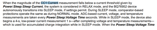
Now we found that the sleep mode of some electronics is not working properly. The electronics are constantly waking up and discharging the battery. When logging data, large spikes are seen on the current, with zero current. We tried calibrating and adjusting the offset, but that did not help. The only thing that has helped is to increase the Power, "Sleep", "Wake Comparator Current", "500", and "mA" to 1200mA. We use a sensing resistor of 0.5mOhm so this value is now at 2400mA. With this setting the electronics goes to sleep.
I am sending the measured values and data.

I would like to ask if you know where could be the problem with the electronics detecting current spikes at zero current and waking up.

Please advise

Regards,

Josel

  • Hi Experts,


    Please see this file

    1385.Files.zip


    Regards,

    Josel

  • Hello Josel,

    The device senses charging or discharging current using the sense resistor connected to the SRN and SRP pins of the device. So, most likely the noises on the sense resistor path will cause this behavior.

    Looking at the schematic, I see they have VSS (IC ground) connected to BAT-. We always recommend to separate the high-current path (BAT-) from the low-current path (IC ground). Often this is done by separating the GNDs with either Net-Tie or a 0-Ω resistor. A reference of this can be found in the BQ76952EVM User's Guide


    Please see our schematic below.


    From the zip file attached, I noticed they have been monitoring CC2 current. The device uses the CC1() current measurement to transition to sleep mode. Please see below. Section 7.3 SLEEP mode from the TRM


    Lastly I would like to comment on the TS2 pin being floating. How do they wake up the device? We recommend to use the TS2 pin to wake the device by pulling the pin low.

    Regards,
    Jose Couso

  • Hi Jose,

    Thank you so much for the tips.

    But we tried it and no result.
    The ground connection is only in the circuit, but there is a separate line on the PCB:
    We also connected the TS2 pin to the ground, but no change.
    The BQ IC still "sees" a current peak, even though the actual current is zero. Any idea why?

    Please advise

    Regards,

    Josel
  • Hello Josel,

    Looking at the layout, the IC (U1) ground is being fed from the sense resistor. We recommend to not use vias and completely separate the Ground connections from the sense resistor. Please see below our EVM layout.


    EVM layout for sense resistor path


    We also connected the TS2 pin to the ground, but no change.

    Regards,
    Jose Couso

  • Another thing that looks concerning is the order of the cell connections. Is VC1 connected to VSS when they attach the battery pack?


    Please reference to Section 16.3 Random Cell Connection Support from the Datasheet

    Regards,
    Jose Couso

  • Hi Jose,

    Thanks for the good ideas. These are good tips for PCB design. But we tested it and no change. We connect the VSS pin directly through the wire to battery pack GND and the peaks on the current are the same.  
    The procedure on connect cells to BMS is: First is to connect battery GND, then the connector, and last connect battery plus.
    Not all electronics have this bad feature. I send photos of fitted ICs. Couldn't they be fake?


    Please advise

    Regards,

    Josel
  • Hello Josel,

    It is hard to tell which IC is fake. Where were the ICs obtained from? 

    They can order a few samples from ti.com and see if the behavior persists.

    Regards,
    Jose Couso