Hi,
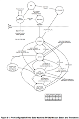
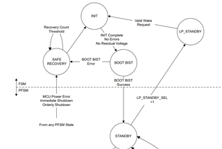
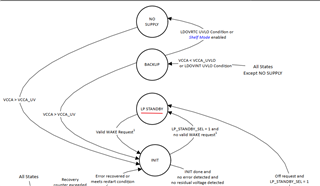
The datasheet illustrates the device power state by the diagram below. Only LP_STANDBY is mentioned, I wonder what about STANDBY when LP_STANDBY_SEL = 0?
Hi,
The datasheet illustrates the device power state by the diagram below. Only LP_STANDBY is mentioned, I wonder what about STANDBY when LP_STANDBY_SEL = 0?