大家
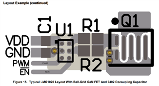
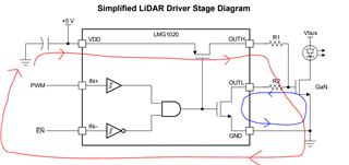
好我參考LMG1020EVM-006並想獲得2ns脈衝寬度鐳射器,我應該如何在PCB上佈局,
1。可以佈置兩層,還是必須鋪設四層?
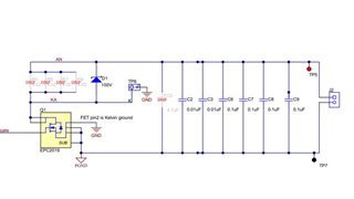
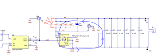
2.電路圖上有PGND和GND。PGND和GND之間的連接只是分層連接,不需要用0歐姆電阻隔開?
3.除了氮化鎵低邊驅動器+氮化鎵場效應管,還有其他方法可以降低ESL嗎?

-
Ask a related question
What is a related question?A related question is a question created from another question. When the related question is created, it will be automatically linked to the original question.