- Ask a related questionWhat is a related question?A related question is a question created from another question. When the related question is created, it will be automatically linked to the original question.
This thread has been locked.
If you have a related question, please click the "Ask a related question" button in the top right corner. The newly created question will be automatically linked to this question.
Hi TI team,
I am planning to use the LP5018RSMR to control six RGB LEDs on a new project in my company and I would like to make sure I connect the LP5018RSMR correctly.
The LP5018RSMR features 18 outputs (OUT0-OUT17) where in my schematics the following connection is made:
OUT0 -> LED1_RED
OUT1 -> LED1_GREEN
OUT2 -> LED1_BLUE
My first question is the following:
Shall the other 5 LEDs be connected in the same order (Red,Green,Blue)? Or can I connect the rest of the LEDs in a different order for instance:
OUT3 -> LED2_BLUE
OUT4 -> LED2_GREEN
OUT5 -> LED2_RED
My second question is regarding to the EN signal. Is it an active low signal? If yes, is an external pull up required or it is internally pulled up?
My third and last question is t what are the benefits of using LP5018RSMR as opposed to using addressable LEDs.
Thank you very much.
Kind Regards,
Kostas Papouis
Hi,
Nice to hear you.
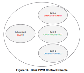
1. If you want to use the bank control function, which can allow you control each color for all RGBs at same time, you need to connect each RGBs in the same order.:

2. EN is an active high signal, pull this pin to high level will enable our device, there is no need for a pull up resistor.
3. With I2C interface, LP5024 is easy to be controlled, and the total solution cost will be lower than addressable LEDs. And our device has bank control function which can allow you achieve more complex animation pattern.
Thanks!
Ives Li
HI Ives,
Thanks for answering my questions.
I would like to ask an additional question and this is related to the connections and location of each LED.
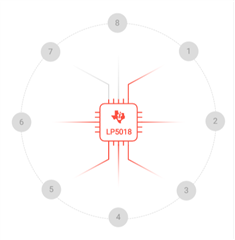
The picture below shows the position and numbering order of each LED.
RGB LED number 1 is connected to pin 1-3.
Is it possible to connect RGB LED number 2 to pin 13-15 on the LP50xx?
Or the RGB LEDs should be connected in order (LED2 - Pin 4-6, LED3-Pin 7-9 and so on) ?
The reason I ask is to ease the routing on my custom PCB.
Thanks.
Hi,
Yes you can connect the LEDs in different why, just note that when you control it to do some dimming effect, you need to configure the related register.
Thanks!
Hi Ives,
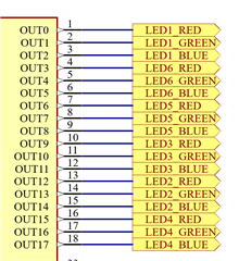
I have designed a custom board with the LP5018 and the following led arrangement:

As you can see the six LEDs were not connected in order. This was done to ease the PCB layout.
You mentioned that I will need to configure the related register when I do some dimming effect such as chasing effect.
I would like to ask if it’s possible to do a chasing effect on my custom board using the LP50 software. If yes, what register do I need to modify?
Thank you.
Hi Kostas,
I can see the six LEDs in your board is not in order, so if you use the LP50 GUI to run the chasing effect, it will light up LED1/6/5/3/2/4 by sequency.
And because this pattern in GUI is controlled by software and cannot be customize, you may need to write your own code to achieve the right chasing sequency you want.
Thanks!
Ives Li
Hi Kostas,
You are welcome, feel free to contact me when you meet problem.
Thanks!