This thread has been locked.

If you have a related question, please click the "Ask a related question" button in the top right corner. The newly created question will be automatically linked to this question.

BQ76952: The question about connection of DSG pin

Part Number: BQ76952
Other Parts Discussed in Thread: TIDA-010208

Hello TI Team,

We are designing BMS with BQ76952. And we are confused about the connection the diode in DSG circuit of BQ76952.

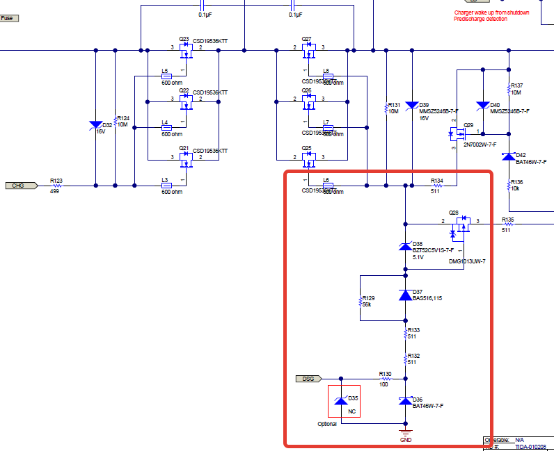
The schematic of TIDA-010208 10s–16s Battery Pack Reference With Accurate Cell Measurement and High-Side MOSFET Control has follows recommendation to connect DSG pin of BQ76952 to discharge MOSFET:

But in the Application Note sluaa09a Multiple FETs with the BQ769x2 Battery Monitors in the Figure 1-1. Typical 7S Series FET Schematic we found out different recommendations to connect the same DSG pin:

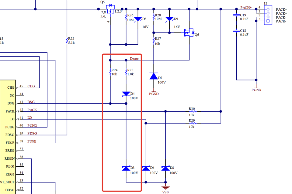
It seems that diode D37 in the schematic of TIDA-010208 has opposite direction than the diode D4 in the schematic in the Application Note sluaa09a Multiple FETs with the BQ769x2 Battery Monitors.

May we ask you to explain us what direction of connection of that diode is better?

  • Dear Sergei,

    D4 functions as a way to increase the turn-off speed of the DSG FET by providing a lower impedance route for capacitance to be drained, and does nothing while DSG is asserted high. Meanwhile, the D37 diode allows a fast turn-off by toggling the PMOS on faster and therefore allowing the gate voltage to connect to Pack+ through a 511 ohm resistor.  

    Both serve a similar application, but there use cases vary. The D37 mode will allow faster turn-offs compared to the D4 setup, but will also run a higher cost for the BOM due to the additional components needed. The main application for this is when you are using multiple FETs in parallel since this creates a larger capacitance at the gate that will need to be discharged to turn off. The low resistance path helps reduce the RC time constant. D4 is a simpler, cheaper solution that is ideal for when there are only a few MOSFETs in parallel along the power path. If you are using 3 or less FETs, this would be the better solution.

    Best,

    Asher Nederveld

  • Dear Asher,

    Thank you very much for the explanation.