This thread has been locked.

If you have a related question, please click the "Ask a related question" button in the top right corner. The newly created question will be automatically linked to this question.

LM5021: LM5021

Part Number: LM5021


My LM5021 based ac to dc converter, which input voltage (100-305)VAC, 50Hz and output voltage 12VDC @ 0.85Amps.  

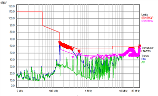
Switching frequency is 123KHz. Power supply is working fine, but conducted emission test as per CISPR 22 class A (Radio disturbance test 150KHz to 30MHz) is failing, Please help me to resolve.

I have tried All filter options but emissions are not  suppressed.

  • Hello,

    Are you passing conducted EMI?

    If you are failing radiated EMI you may have to put the design in a metal enclosure grounded to chassis ground.  This works as a Faraday cage to reduce radiated EMI.

    Some designs have EMI radiate off the power cord. To resolve this generally designers will rap the power cord around a ferrite toroid.  This will act as a common mode choke and help reduce radiated EMI.  Please note that the toroid and wrap need be as close to the faraday cage/enclosure as possible.

    Regards,

  • I hv facing issues in conducted emission test not radiated EMI. I hv shared the graphs as well. need support to tune the filter values for getting the it pass.for more details refer my conducted EMI graph.

  • Hello,

    I am reviewing your inquiry and will get back to you shortly.

    Regards,

  • Hello,

    It is the radio disturbance comment that you added to your post that made me think it was radiated.

    I looked at what you are using for EMI filter and it looks like a common mode choke.  Since you don't have Y capacitors at the input of the common mode choke to ground you might be failing for common mode noise.  I would suggest adding Y capacitors from the input to the common mode choke to chassis ground.  This could help.

    after that I would set the pole frequencies at the filters to a decade below the noise they are failing to attenuate the noise.  fp = 1/2*3.14*(L*C)^0.5.

    The following link will bring you to training material that shows how to properly setup an EMI filter.

    https://www.ti.com/lit/ml/slyp757/slyp757.pdf?ts=1687981841276&ref_url=https%253A%252F%252Fwww.ti.com%252Fsitesearch%252Fen-us%252Fdocs%252Funiversalsearch.tsp%253FlangPref%253Den-US%2526searchTerm%253DEMI%2BFiltering%2526nr%253D14735

    Regards,

  • Y capacitors are present at the output of the common mode choke to ground. but no luck.

    I have also added the Y capacitors (2.2nF) at the input side of the common mode choke along with the existing filter but still there is no major difference in the noise reduction. I have tried with different  common mode choke values from 3.3mH to 33mH but no change in results.

    When i added one more Y capacitor parallel to C10 then only noise get reduce and Passed by 1dB only.

    Then I added one Y capacitor between DC positive and Transformer secondary side ground then noise is further reduce and passed by 3dB. still there is no major break through in the results.

  • Hello,

    It is good that you have added the why capacitor across the flyback transformer.

    Have you try adding ones to the input?  This may help as well.

    I notice that you have snubber across D1 you are are not using.  Have you looked the ringing at the switch nodes? Dampening this ringing with the snubber could also help you pass EMI.

    Regards,