This thread has been locked.

If you have a related question, please click the "Ask a related question" button in the top right corner. The newly created question will be automatically linked to this question.

TPS2H160-Q1: Design questions

Part Number: TPS2H160-Q1

Dear team,

we have some questions regarding TPS2H160BQPWP

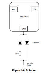
1) if reverse-current protection is required, do we need to implement booth method1 ( adding a blocking diode) and method2 ( adding GND network) or only one of the method?

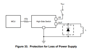
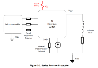
2) As per slvaes9a the loss of ground  or loss of battery we need following approach on the picture 

In case we have a blocking diode on Vs (methode1)  do we still need the Gnd network and series resistor if we want protect against loss of gnd and loss of battery?

3)Open-load detection when channel off, DS recommends 20k pull-up while the EVm uses 10k pull-up, how is the pull-up selected ( value and power rating) ?

4) can we connect THERM direct to gnd without pull down resistor?

5) can we connect DIAG_en direct to 1.8V , diagnostic always on ?

6) on what pins are the series blocking resistors needed in case of loss of battery?

7) Can we use BAV99 instead of BAV199? when using GND network.

Best Regards,

d.

  • Hi d,

    1) It is not necessary to have both methods of reverse-current protection in the same application. Method 1 (blocking diode) protects both the device and load, while method 2 (GND network) protects only the device.

    2) For loss of battery protection, there is the alternative of adding a flyback diode in parallel with the load (shown in the picture below). This would still require the series resistors, but not the ground network. As for the protection against ground loss, the solution shown in the figure you referenced (1.6) is only necessary if there is a loss of module ground and a low-impedance path exists between the input supply line and the module ground of the HSS. If these conditions are not a concern in your application, the solution can be skipped.

    3) While I gather more information on the reason for this difference between the DS and EVM, I would recommend sticking with the DS value of 20k. 

    4) I assume you are referring to the THER pin. If so, that can be connected directly to gnd.

    5) The minimum logic high voltage level for logic input (INx, DIAG_EN, SEL, THER) is 2V. So while diagnostic can always be on, the voltage at the DIAG_EN pin would have to be at least 2V.

    6) The series resistors should be in all pins that make connection between the HSS and MCU.

    7) Yes, the BAV99 is acceptable when using the solution in figure 1.6.

    Best Regards,

    Gabriel

  • Hi Gabriel,

    the picture that you posted is not showing for me, pleas can you repost?

    Br,

    d.

  • Hi d,

    Here it is:

    If you still can't see it, it is Figure 33 on the datasheet (section 8.3.7.3).

    Best Regards,

    Gabriel

  • Hi Gabriel,

    we wan to use the HSS on FpdLink PoC camera ( so we don't have inductive load, only the small inductance of the cable ) for the current limiting feature ( Overload Detection).

    -> What can happen is Short-to-GND and short to 12V (VBATT), we don't need the reverse polarity protection.

    -> What would you suggest for the Short-to-GND and short to 12V situation in order to protect the device and the load?


    Best Regards,

    d.

  • Hi Garbriel,

    any update on this?

    Best Regards,

    d.

  • Hi d,

    The TPS2H160-Q1 offers Short-to-GND protection by current limiting. For the short to 12V situation, the device doesn't provide protection but is able to detect it (discussed in section 8.3.6.3 of the datasheeet). Then, based on the device diagnostics, a software or downstream solution could be used to protect the load.

    Best Regards,

    Gabriel