This thread has been locked.

If you have a related question, please click the "Ask a related question" button in the top right corner. The newly created question will be automatically linked to this question.

LM5176-Q1: LM5176-Q1 ICs getting damaging (10-12 qty damaged) during start up

Part Number: LM5176-Q1
Other Parts Discussed in Thread: LM5176

Hello TI Team,
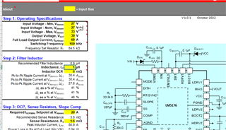
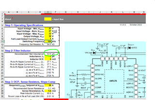
We are using LM5176QPWPTQ1 for buck-Boost convertor.
We are facing LM5176 ICs getting damaging and until now 10-12 qty have been damaged and still there is no output voltage (Load was 0A (no load) or small load 0.5A etc). Below is the our schematic with brief system specs.

Vin (min): 27V
Vin (max): 33V
Vout (nor): 30V

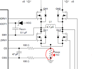
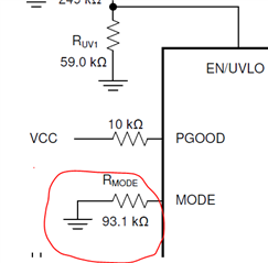
Please find below attached schematic

LM5176_Testing_Schematic_1.pdf

Request you kindly do the support on the same.

  • below is the input (blue) / output (Red) waveform. After 1st start LM5176 ICs got damage (mean No output signal and output +ve to output gnd showing low resistance (~100 ohm)).

  • We have done some exercise, we had measured all damaged ICs ohm, mean measured resistance between each ICs pin (from 1 to 28) wrt AGND pin for all damaged ICs. Surprisingly it is observed that every time same pins getting damaged as shown in below sheet.

    No color value are in Mega ohms
    Red color value are in ohms (R)
    Other color value are in K ohms


    TI team could you please support us in this issue.
    Thank you!

  • Hi Shankar,

    Thanks for reaching out. You can try to increase the input capacity and increase the SS capacitor in order to stabilize the input voltage while ramping up.

    Best regards,

    Moritz

  • HI Moritz,
    Thanks your response,
    I hope you had seen above schematic and could you please let's us know what value would be place for input and SS capacitor.

  • Hello Shankar,

    Did you check your design already with the quickstart calculator of LM5176 https://www.ti.com/lit/zip/snvc208 ?

    For the input capacitor, please add input capacitance until the input is stable during startup. This is heavily dependent on the input source and the connection to the board, so we cannot recommend a value there.

    For the SS cap, you can increase it by a factor of 2 or 4 or even go higher for test purposes. At the moment I think, it is important to make sure that the device does not get damaged and only then you can start to debug more in detail.

    Best regards,
    Brigitte

  • Hello Brigitte,
    Thank you for your reply.
    We already went through your " Quickstart Calculator" also this was update to Moritz in few weeks before.
    Anyway, the Good news is that, now we are getting output (30V) for above 30V vin mean working in buck mode but we are not yet tested with load. Yet be test with loads.

    Important: For lower input voltage (less than 30V) the output remain same as input. i,e if input is 27V then output getting 27V without load and also for lower (500mA) load. 

    We also tried this with 26Vin, 27Vin 25Vin etc but output not getting 30V showing same as input. 
    Which mean "BOOST" mode still not working. I hope, you get chance to go through with shared schematic an could you please let us know what is the reason "BOOST" mode is not working?

    Note: Below is the Boost mode input & output waveform for your reference. After 236mSec the output voltage getting down.

    Red => Input 27V, 3 or 5A current
    Blue => Output ~27V without & with load (500mA) .


  • Hello Shankar,

    The measurements are taking on the circuit that follows the shared schematic above, right?

    Can you please check the boost switch node when the output starts to drop? Is it possible that the device is going into hiccup mode?

    Best regards,
    Brigitte

  • Hi Brigitte.
    Okay will share Boost switch node waveform soon.
    Meanwhile could you please do let us know Rmode related.

    We had connected 93.1K ohm at LM MODE pin (pin no.4). Could you please do let us know at what current system enter into the hiccup mode for with RMode = 93.1K.
    Can we increase / decrease this Rmode resistance value to shift the hiccup mode at high current value ( late say above 90A) if so what would be the Rmode value.


    FYI: In our system 
    Rsense value is 1.5m ohm
    Rmode value is 93.1K


  • Hi Brigitte.
    Below is the boost node waveforms.

    Blue => input voltage (25V)
    Green => SW1 node waveform
    Red => SW2 node waveform
    Yellow => Output waveform

    Seems system getting restart after every 115mSec.

  • Hello Shankar,

    This looks like hiccup mode. This happens if the device is getting into current limit. Please check if your peak current supports the boost mode. In boost mode the peak current in the inductor is bigger than the output current.

    Best regards,
    Brigitte

  • Hello Brigitte,
    As I had mentioned above the Rsense (1.5m Ohm) and Rmode (93.1K) for that purpose. Since the above waveform was without load (mean 0A & 0.03A) load still how the hiccup mode is activated?

    Also we didn't get answer for below query which was requested in previous message.

    We had connected 93.1K ohm at LM MODE pin (pin no.4). Could you please do let us know at what current system enter into the hiccup mode for with RMode = 93.1K.
    Can we increase / decrease this Rmode resistance value to shift the hiccup mode at high current value ( late say above 90A) if so what would be the Rmode value.

  • Hello Kanki,

    Just to understand your circuit, I reviewed again the measurements you sent and I can not see in any of the measurements the set 30V. So something is not working as expected, as I expect the output to reach the set voltage during normal operation, especially when you mention that there is no load.

    Please check the voltage from CS to CSG while you are operating the device in boost mode only.

    MODE pin does not influence the hiccup timing or current threshold. It just defines if the device is operating in hiccup or not. The device goes in hiccup mode if it operates in overcurrent for several consecutive cycles. In normal operation the device should not go into hiccup at all.

    Best regards,
    Brigitte

  • Hello Brigitte,
    Yes, we also curious to know from you, why it is not working even for no load.
    Below is the CS to CSG waveform.

    Blue => input 25V
    Red => Input current
    Green =>Output voltage (only 24.41V not getting 30V)
    Yellow => CS wrt CSG waveform


    Zoomed waveform:


    Full waveform:


    Please suggest further action on the same.

    Looking forward for your quick reply.
    Thank you!

  • Hello Brigitte,
    Yes, we also curious to know from you, why it is not working even for no load.
    Below is the CS to CSG waveform.

    Blue => input 25V
    Red => Input current
    Green =>Output voltage (only 24.41V not getting 30V)
    Yellow => CS wrt CSG waveform


    Zoomed waveform:


    Full waveform:


    Zoomed CS & CSG waveform with timing:


    Please suggest further action on the same.

    Looking forward for your quick reply.
    Thank you!

  • Further update.
    Now we have disabled Hiccup mode (mean, 200K ohm connected between MODE pin and GND).
    Still there is no expected output (30V) and it is showing same as input voltage.

    Below is the waveform
    Blue => Input voltage (20v)
    Green => Output voltage (20V, expected is 30V)
    Yellow => CS & CSG waveform


    Awaiting for your suggestion
    Thank you!


  • Hello Brigitte,
    Any update ?

  • Hi Brigitte & TI Team,
    Gentle reminder for your reply.
    Thank you!

  • Hello Shankar,

    To be honest, my recommendation would be taking an LM5176 EVM, exchanging the components as calculated for your case by the quickstart calculator and check if then your converter is operating. As your board seem not to work, I think starting from a known good layout is helpful.

    Best regards,
    Brigitte

  • Hello Brigitte,
    Okay, Noted. 
    Could you please share LM5176 EVM board gerber source file?

  • Hello Shankar,

    Please find them in the EVM folder here: LM5176EVM-HP Evaluation board | TI.com under design files.

    Best regards,
    Brigitte

  • Hello Brigitte,
    Ya, We have checked in that design files but we didn't get gerber file. Could you please share here?
    Thank you!

  • Hello Shankar,

    Ah, sorry, I expected not that you prefer gerbers over CAD files. Give me some days to get these prepared.

    Best regards,
    Brigitte

  • Thank you Brigitte.
    Would be appreciated, if you share these files as early as possible.
    Awaiting for your these files data.
    Thank you!

  • Hello Shankar,

    We will deliver the gerber files until end of this week.

    Best regards,
    Brigitte

  • Hello Shankar,

    Please find the gerber files here: SV601348A_Gerber.zip

    Best regards,
    Brigitte

  • Hello Brigitte,
    Thank you for sharing this file.

    BTW, As we are rechecking "quick start tool" excel sheet which was shared by TI team. We have one query
    Our system max load is 60A and based on this we are getting inductance value as ~1uH.
    But as you know we are doing testing our system with No load Or min 1A load.
    considering this load the calculated inductance value (from Quick start sheet) it is showing higher value (53.5uH)

    So for our system 
    Vin min 27
    Vin Max 33
    Iout :0 to 60A Max

    Note: Could you please guild us which inductor value should we use for our system (1uH or higher)?

    Awaiting for your valuable quick response.
    Thank you!


  • Hi Shankar,

    You should use 1uH inductor for your application.

    But I think it is really challenging for you design now:

    You used TO220 MOSFET which has a high parasitic inductance, please check SW1 and SW2 stress (positive and negative spike); I believe you cannot meet the Absolute Maximum Ratings below.

    Please check if adaptive dead time function properly.

    Also the conduction loss is very high at 60A.

    Best Regards,

    Feng Ji

  • Hello Feng,
    Thank you for valuable reply, sure we will consider 1uH.
    We are updating schematic, in fact we would like to share our updated schematic (not in public) so could you please share email Id or how to share it to you? Or Requesting you to please send friend request so that will share the same.
    Awaiting for your response.
    Thank you!

  • Hi Shankar,

    You may send friend request.

    Best Regards,

    Feng Ji

  • Hi Feng,
    I sent request, Please accept request.

    Our schematic is ready for sharing. Awaiting for you acceptance and Kindly acknowledge once you accepted.

  • Hi Feng,
    Thanks for accepting request. I have shared complete schematic to you.
    Kindly share your valuable feedback on same PDF.
    Thank you! 

  • Hi Shankar,

    Let's discuss in mails.

    Best Regards,

    Feng Ji