Other Parts Discussed in Thread: LMV431
Hello everyone,
I am facing a problem in the start-up of a TLV431 used as a comparator.
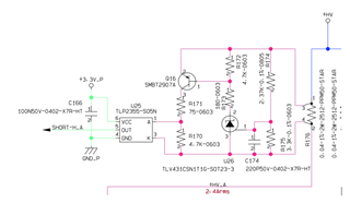
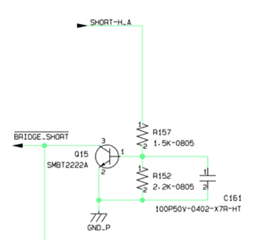
In my application, I use a TLV431BCDBZR as a comparator to sense when the voltage across the resistance R176 is higher than 2.13V. When this happens the voltage at Vref exceeds 1.24V and so U26 starts conducting cathode current, Q16 goes from an interdiction state to a saturation state, driving a logic circuit and commuting the signal BRIDGE_SHORT from high logic state to low logic state.
To simulate its operation I generate a voltage pulse with an amplitude of 3V across R176. Everything is working well if the pulse rise time is higher than 10us, when it is lower TLV431 starts conducting cathode current in advance.
rise time:10us
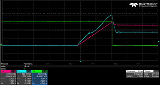
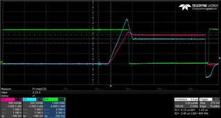
rise time: 4us
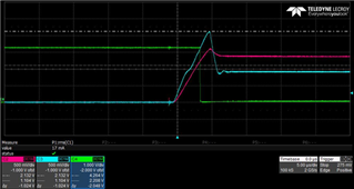
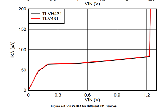
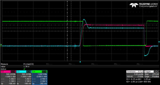
In the picture I attached you can see the voltages waveforms I measured in my circuit at different pulse rise times. The light blue curve shows the voltage between the TLV431 cathode and anode. The red curve shows the voltage between TLV431 ref pin and anode. The green curve shows the voltage between the signal BRIDGE_SHORT and GND_P.
I tried to use an LMV431BCM5 also and it is working well if I have a rise time above 1us.
rise time: 4us
rise time:1us
I would like to use a TLV431 because it is cheaper than an LMV431, so is it possible to improve his behaviour in any way? Otherwise could you suggest to me a component with a price similar to the TLV431 and witch has an appropriate respose?
Thank you,
Davide