Other Parts Discussed in Thread: LM317,
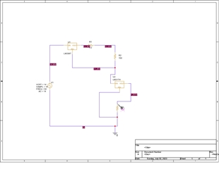
Hello, I am trying to run this circuit using Pspice, however, I didnt get the desired output current which is 1A. Can you help me? Thank you in advance
This thread has been locked.
If you have a related question, please click the "Ask a related question" button in the top right corner. The newly created question will be automatically linked to this question.
Hi Nurul,
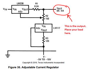
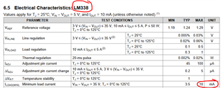
It looks like you are trying to simulate this circuit in the datasheet. The output of this circuit is between the LM338 and LM317, labeled Iout in the image below. You should not expect 1A flowing through R3. R3 = 120 ohms, and the internal reference is 1.24V. So you should expect about 10mA across R3. Therefore the LM317 sinks a constant 10mA despite the voltage on Iout node, which keeps the LM338 regulating properly as the LM338 has a minimum load current requirement of 10mA (worst case).
Thanks,
Stephen
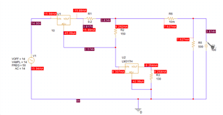
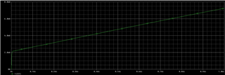
hello Stephen, thank you for answering my question. I had tried simulating the same circuit with the load (a 12V Li-ion battery) and I construted it using resistors and capacitor. but however I still didnt get 1A as the output current. can you perhaps show me which part of the circuit did I do wrong? thank you in advance!
Hi Nurul,
You'll want a DC source for V1, not an AC source. If you set your DC source to something like 10V, then you'll need to configure R5 to be no greater than (Vin - 3) / 1A = (10V - 3V) / 1A = 7 ohms in the simulation. You shouldn't need the R6 resistor, you can delete that.
Thanks,
Stephen
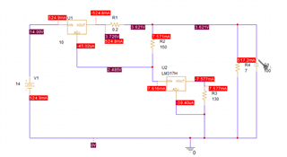
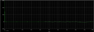
hello, i have change the value of resistor to 7ohms but i still cant get the desired result. what do you suggest?
the load is supposed to be a 12v battery as i was trying to charge the battery.