This thread has been locked.

If you have a related question, please click the "Ask a related question" button in the top right corner. The newly created question will be automatically linked to this question.

UCC21732-Q1: Tripping issues in the gate driver IC.

Part Number: UCC21732-Q1


Dear sir,

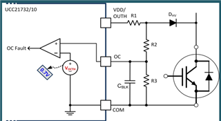
We are developing a 20kW three-level neutral point clamped PFC. For that the gate drivers we are using is UCC21732QDWRQ1. The layout for the gate driver we have designed is same as provided by TI. The DESAT value we are setting is 80A. Our per phase current requirement is 35A. But still we are facing tripping of the gate driver after 10kW of power rating. We are unable to get that problem. Kindly help us to resolve the issue.

Thanking You

Manoj A. Waghmare

  • Hello Manoj, 

    If you could provide below information, it could help us with debugging. We'll review the information provided and get back to you. 

    • Schematic and layout of the gate driver portion
    • Condition when DESAT trips (Current level? Bus voltage level? etc.)
    • Waveforms of the following signals when DESAT trips: 
      • Voltage on DESAT pin
      • Vgs
      • nFLT pin
      • RDY pin (to make sure the tripping is not caused by UVLO)

    Thank you! 

    Best, 

    Vivian Qi

  • Sir,
    This issue we have already asked earlier bearing number CS1296763. The concerned waveforms are already been shared with last query. The gate driver is tripping at 800V, 25A bus voltage and current conditions
    UCC21732_GATE_DRIVER_7000.SchDocAlso PFA of the gate driver schematics.
    One more important thigh i would like to bring in notice that. As alternative we are using other make gate driver (1ED3491MC12MXUMA1) having some common layout. But with that we are getting our desired output of >20kW. Why this is so?
    Kindly go through our queries and give us some good solution.
  • Hello Manoj,

    Thanks for providing the schematics. I have noticed that the schematic you've provided is missing the DHV diode and instead you have a R35 resistor (please refer to the diagram below). Please replace R35 with an appropriate diode and let me know if it works. We also recommend using an external miller clamp gate resistor (R116 in the schematics)

    Hope this helps!

    Best,

    Pratik

  • The DHV diode we have already connected in the power PCB. Still this issue is present

  • Hello Manoj,

    As per our guidelines, the CS number shared is through a different portal which we don't have access to. E2E is a separate support entitiy. Therefore all the relevant info and waveforms have to be posted or shared here. Can you please share the previously mentioned waveforms here to help us understand the query and situtation better?

    Thanks & regards,

    Pratik

  • Now all the gate drivers are mounted on the converter module it is difficult now to measure the actual waveform. Please give us some possible solution regarding this or any other approach to access the previous CS number. 

  • Hi Manoj,

    Thanks for reaching out. As I've previously mentioned we cannot access it as it is a completely different forum. Please share the waveforms if you find it, if not I'm afraid you would have to retake the measurements and share it here or I can give you my email address in personal chat if you don't want to share them publicly. I'm going to close the thread, please re-open a new thread when you acquire all the waveforms and required data.

    Best,

    Pratik

  • Thank you Pratik for the reply. Before closing the thread, can you please let us know if TI people is using the same gate driver for 10kW to 20kW converter applications?

  • Hi Manoj,

    Yes, a lot of customers are using the UCC21732-Q1 device for even higher power applications. 

    Best,

    Pratik