This thread has been locked.

If you have a related question, please click the "Ask a related question" button in the top right corner. The newly created question will be automatically linked to this question.

TPS2372: Advanced Adapter ORing Solutions using the TPS2372-3

Part Number: TPS2372
Other Parts Discussed in Thread: TPS23753, , LM5022, TPS2373

Hi,

please help implement adapter priority over POE PSE input. 

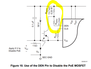
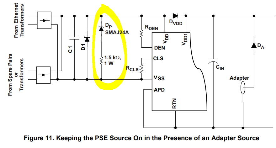
according to "Advanced Adapter ORing Solutions using the TPS23753 " I can use "Option 3 Adapter Priority" only, since TPS2372 has no disable pin or adapter detection pin correct?

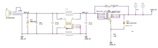
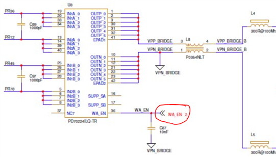
design contain PD70224 bridge, TPS2372-3 and LM5022 flyback.

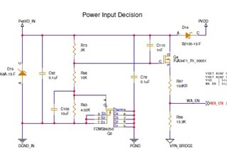
when inserting power from an external adapter, we have a priority circuit to control the enables of the ICs, this should turn off the bridge and make it act as a rectifier. Now I need to add a solution to disable the TPS2372.

I want to add another branch from the Q4 drain (in the schematic it is placed incorrectly, the drain and source are opposite) to disable the TPS2372 according to the application note option 3 but without an optocoupler. 

please help with how to implement this. 

  • Hi Aviv, 

    TI US is currently on holiday and will return July 5th, thank you for your patience!

    Thanks and Regards,

    Raymond Lin

  • Hello Aviv,
    Thank you for your patience.
    If you are seeking a solution that does have the APD pin, the TPS2373 has similar functions with the added APD pin that can make this implementation easier.
    For a non-complex design, it would be easier to use the TPS2373-3 along with a diode rectifier bridge.

    With the TPS2372, it is possible, however it is a much more complicated design.
    You can connect DEN to Vss, but this is typically done with an optocoupler.
    Rather, a possible solution is you could try an oring circuit with option 2 and power on the adapter first, then turn off the TPS2372 by pulling DEN to VSS. This would give you a hitless transition from pd to adapter power.
    It is possible to use option 2 without the use of an APD pin, instead you would just have to ensure there is a diode from V_adapter to VDD and the ground of the adapter is referring to RTN (PGND).

    After adapter is inserted, the PD should be disabled for adapter priority.

    Another note is, we notice you are using an ideal diode rectifier.

    We have seen some other customers have issues when using an ideal diode rectifier when the adapter is on, so you may consider adding a node to disable the ideal diode rectifier.

    You mentioned wanting to add another branch from the Q4 drain, may I ask where you were planning on connecting this to?


    Thank you,
    Sarah

  • Hi,

    We are based on the reference we got previously from TI, PMP23181AP(001). design is already done but has the issues I mentioned above. this means I cannot change to TPS2373. 

    the change in the schematic is an ideal bridge instead of rectifier diodes to maintain low power loss and heat.

    An additional circuit where added as option 3 suggested if an external adapter is presented, a ground connection is made and also the ideal bridge is changing its work mode to rectifier diodes. what is missing is the ability to also disable the output of TPS2372 if the adapter is present that I didn't design and need now to reconsider.

    I want to add another branch from Q4 to DEN to disable the PD, this is possible only with an additional optocoupler?

    can you suggest an optocoupler to use? also, need to make changes in the DEN resistor to do so?

    thank you, 

    Aviv.

  • Hello Aviv, 

    I see. Yes, for option 3 you will need to design the circuit to disable TPS2372.

    The connection to DEN will need an optocoupler for the best results. Any optocoupler that has a rating of at least 70 V , and ideally has a CTR around 300% - 400% will do. Example: 140100146000 from Wurth Elektronik

    And yes, the DEN resistor will need to be changed into a voltage divider, with two separate resistors and the connection from the optocoupler in the middle, as depicted here:

    Choose R_DEN1 to be a value between 12kOhm -15 kOhm
    and R_DEN2 = 24.9kOhm - R_DEN1

    Best regards,
    Sarah

  • Hi,

    I stitch on board an optocoupler and changed the DEN resistors according to your recommendation. 

    results are as follows - 

    1. if the 48V external adapter is connected then insert PSE input - the external adapter is a priority and PD is not working. - this is ok

    1.1. if disconnect 48V while PSE is presented power is turned off then PD is activated and turned on - this is not ok, no seamless transition.

    2. if the PSE is connected and PD recognizes it, then insert an external 48V adapter - PD is not turned off and PVDD remains 56V.

    2.2. if disconnects PSE while 48V is presented power is seamlessly transitioned to 48V without being turned off but PD LED indicators remain active - why?

    my question is

    1. is this option (3) allowed a seamless transition from the external adapter and PSE input without power being turned off?

    2. if not, TPS2373 is capable to do so? 

    3. why when disconnecting PSE and using an external adapter the PD LEDs are still on? 

    thank you,

    Aviv.

  • Hello Aviv, 

    1. Seamless transition is attainable for option 3, have you tried implementing the following circuit to ensure power stays on during transition?

    Additional information for this can be found in section 3.6 of the Advanced Oring Solutions document.


    2. TPS2373 is also capable of seamless transition, it is more easier than TPS2372 to implement because of the APD pin. 

    3. Sorry, I'm unsure what you mean here. Are you referring to the LEDs D8,9,10 ?

    Thanks,
    Sarah

  • Hi,

    It will be better to start again and implement TPS2373 with the prioritized external adapter over the POE. 

    the updated design should support these options of power input - 

    1. DC external adapter only or POE only

    2. DC external adapter prioritized over the POE input where the seamless transition between them should be implemented.

    2.1. if DC is connected then POE -> no PSE detection

    2.2. if both are connected on power up -> DC external adapter is prioritized. 

    2.3. if DC and POE are connected and then DC disconnected - a seamless transition to POE

    I can send you a full schematic for implementation support if needed, please advise email to send to.

    please help implement those requirements. 

    thank you

  • Hi Aviv, 
    Sure thing. You can reach me at s-lao@ti.com

    Thanks,
    Sarah