This thread has been locked.

If you have a related question, please click the "Ask a related question" button in the top right corner. The newly created question will be automatically linked to this question.

TPS65988DK: 2 USB C Port peripheral defalut settings for TPS6598x Application Customization Tool

Part Number: TPS65988DK

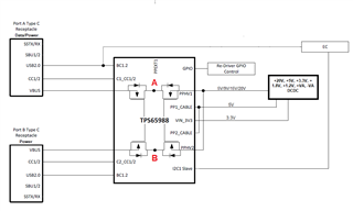
We are making a product that will use the TPS65988DK as below:
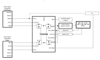
The product is expandable.  It will operate in its simplest form with the USB C port A connected to a PC.  As other components are added to the system, more power is required and the second port is needed for additional power.

Power from only one USB port will be used at a time.  The EC needs to be able to know what power is being provided, including what voltage and maximum current.

A use case that we hope can work is to connect the device to a laptop, then connect the laptop's USB C power supply to the device.  The device would make any leftover power available to the laptop.
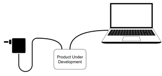
I have a TPS65988DKEVM and have been working with the TPS6598x Application Customization Tool.  Can you provide a .prj file that would do what I need or that would be a good starting point for me?

Thanks,

David


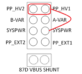
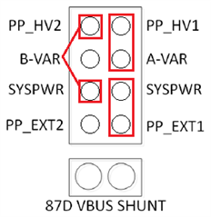
  • I would like to get the EVK set up as we would like for the product.  In order to do so I believe that I will need to set the jumpers as follows: 

  • Hi David,

    Thanks for reaching out.

    Do you need BC1.2 support as per your block diagram?

    BC1.2 feature is not available on 988DK.

    Thanks, 

  • My understanding is that I do not need BC1.2.  What in the block diagram indicates that I may need BC1.2?  

  • Here is more clarity on the use case

    • USB-C Port 1 of the product may be connected to a USB-A or a USB-C terminal on a laptop or USB Hub.
    • When only USB-C Port 1 is connected, the product will limit its capabilities based on the power available at Port 1. This will be 5V 900mA.
    • USB-C Port 2 must be connected to a USB-C charger. When Port 2 is connected, the product calculates maximum power required for itself and offers the remaining power to Port 1.

    Can you provide a starting point .prj file for this?

  • If USB-C Port 1 is connected to a USB-A port on a computer, the product's capabilities will be limited to what it can do with 5V, 900mA of power.  If it is connected to a USB-C port on a computer, it will limit its capabilities to what power that port offers.

  • Thanks for the clarification.

    I'm working on it. Allow me time till Monday to get back to you

  • Hi David,

    Attached is a sample .pjt that should work for you with some system specific changes required.

    Summary of what I changed:

    • Added 2 new virtual devices, you can make gpio0 high or low to choose between the 2 different configs/ virtual devices
    • Based on when adapter is not present, and when external adapter is present, you can toggle gpio0 to toggle between the 2 settings and leave the PD to take care of the re-negotiation on its own. The re-negotiation part is taken care of in reg 0x6c

    What needs to changed:

    • Based on the balance power from your adapter and the active RDO, you'll need to change Source PDO2 of device marked as (0x2).

    Hope this helps, let me know if anything else is required

    TID1245322_1007_VT0.pjt

  • Thanks Varun!

    This is what I have done:

    • I loaded the project you provided into the Application Customization Tool
    • I selected Binary->Flash From Current Project
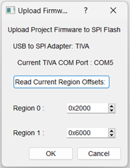
    • I went with the default:  \
    • It showed the message ERASING, then PROGRAMING, VERIFYING, and REBOOT

    Here is how the system performs:

    • Port A will only receive 5V regardless of what USB-C source is connected.  Port B will receive the maximum voltage available up to 20V
    • SYS get's its power from the first USB-C port attached. 
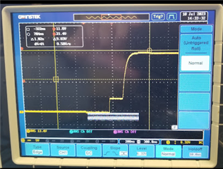
      • If I connect Port A to a laptop, then Port B to a charger, VBUS on port B goes to 20V 
        Port B VBUS

        and VBUS on port A goes to 5V, SYS is 5V. 
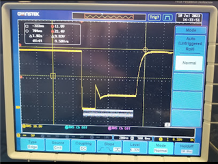
      • If I then unplug port A, SYS drops to 0V then up to 15V. Port B also resets- it goes from 15V to 0V, 5V then 15V
        Port B VBUS when Port A disconnected
      • If I connect and disconnect Port A while Port B is connected, SYS stays at 15V and Port B VBUS stays at 20V

    Using a PD analyzer,  I can see that PORT A does not become a source to provide power back to the laptop.

    In your description, what do you mean by "adapter" is this the USB-C charger connected to Port B?

    I have created a modification on the EVM that allows me to pull gpio0 to 3V.

    The system seems to operate identically whether gpoi0 is high or low.

    How do I:

    1. Make Port B the port connected to SYS (PPHV) when both Port A and Port B are connected.  
    2. When Port A and B are connected, how to make (Port B available power minus 30W) offered to Port A- so that the laptop connected to Port A could be charged?

    Best regards,

    David

  • Hi Varun,

    I have more questions.

    "Added 2 new virtual devices, you can make gpio0 high or low to choose between the 2 different configs/ virtual devices"

    • -I do not understand how to use these 2 virtual devices

    "Based on when adapter is not present, and when external adapter is present, you can toggle gpio0 to toggle between the 2 settings and leave the PD to take care of the re-negotiation on its own. The re-negotiation part is taken care of in reg 0x6c"

    • In your message what are you referring to by "adapter"? 
    • Should the project you provided respond differently when holding gpio0 low or high?  Is this what you mean?"

    "Based on the balance power from your adapter and the active RDO, you'll need to change Source PDO2 of device marked as (0x2).

    • My understanding from the above is that I will need ta calculate the power available and set the PDO accordingly.  Could you please send a .prj file that has this set for the PDO to be 20V, 1A so that I can see an example of the settings?  I will use a USB C charger that can supply 20V, 4A for the test.

    I would really appreciate being able to chat with you in real-time to help me get things working.  If this is possible, please let me know a time that can work.

    David

  • Hi David,

    Can you please share a brief block diagram of the system?

    I'm specifically looking for the power path and dcdc architecture to know how the vsys gets generated and how you switch from a source to sink and vice-versa.

    Thanks,

    Varun

  • Hi Varun,

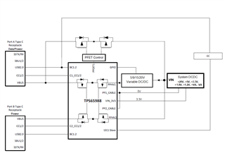
    This is the block diagram of the system

    There is no battery.  The 5V or 9V or 15V or 20V is what is received via VBUS from the USB C ports.  This is then converted to +20V, +5V, +3.3V, 1.8V, 1.2V, ++VA and -VA that is used by the system.

    The system can operate with only Port A connected to a PC.  In this case switch A would be on and would supply power to the system.  When Port B is connected to a USB-C charger (both Port  A and Port B are now connected), this becomes the source of power to the system.  Switch A would be off and Switch B would be on.  .  The system will use a maximum  of 30W.  Any leftover from this is to be offered back to Port A to be used by a laptop for charging.  A single voltage would be offered back to port A since the only option is the voltage received on port B VBUS.  If Port A wants to be a sink Switch A would then be turned on.

    David 

  • Hi David,

    There's a small problem here.

    Since PPHV1 & PPHV2 are shorted together, portA will not be able to come up as a source if the PDO negotiated on portB is >5V.

    PortA has to come up as a 5V source on the initial implicit contract and then negotiate a PD contract to meet the notebook demands (typically >5V).

    Thanks,

    Varun

  • OK,  It looks like I will need to use external switches to have the ability to put power back to Port A.  A new block diagram is needed.

  • Hi David,

    Do we have an updated block diagram for this one?

    Thanks,

  • Jumpers on the EVM would be this:

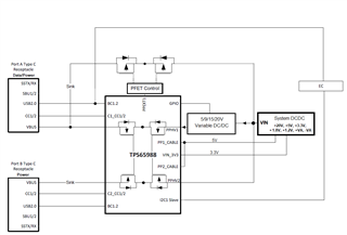
  • This is the block diagram with the sink paths identified

  • When only Port A is connected to a Laptop, the system will enable less features to accommodate the power received.

    When Port B is also connected, the system will use the power from this port  up to 30W.  If more power than 30W is available, then available Power from B minus 30W is offered to Port A. So if a 65W USB-C charger is connected to Port B, the following PDOs would be offered to Port A:

    • 5V, 3A
    • 9V, 3A
    • 15V, 2.3A
    • 20V, 1.75A

  • Hi David,

    The jumper settings look correct.

    You can use the attached .pjt file and follow the below steps:

    When GPIO0 goes low to high, it selects the virtual device 1. It would be the case where the device
    works only on NB power and no external power adapter is connected.

    Once and external adapter is connected and detected, GPIO0 can be transitioned from high to low to
    choose the virtual device 2. This would change the following config for port1, type-c state machine,
    source caps, and automatically send source caps to the NB. You can modify the PDOs for this virtual
    device 2 based on the power calculations.
    The virtual device feature would take away the headache of sending 4CCs to renegotiate and to get a
    basic template for setting the new source/sink caps.
    Thanks,
  •  Hi Varun,

    Using the .prj file you provided does the following:

    The EVM negotiates power from the two USB-C ports. If only a NoteBook (is this NB in your description?) is connected to Port A, then SYS is powered with 5V. If Port B is then connected to a USB-C charger (is this external power adapter in your description?) SYS received the voltage from the Port B (15 or 20 volts from my tests, depending on the charger used)

    Looking at the signals PA_PP_EXT_ENABLE is asserted immediately after connecting Port A to the NB. Output of U3 is Low.

    When a USB charger (20V max) is connected to Port B, PA_PP_EXT_ENABLE remains high, but the output of U3 goes low. This must mean that VBUS2 to PP_HV2 was turned on and the voltage across Q4 an d the output of comparator U3 is what turned off the external path.

    I also tried the following:

    1. connect port A to NB

    2. Assert GPIO0 from 0 to 3.3V (low to high): VBUS1 momentarily goes off then back on

    3. Connect Port B to USB-C Charger

    4. Observe that SYS_PWR and VBUS2 goes to 20 V

    5. Assert GPIO from 3.3V to 0V: VBUS1 momentarily goes off

    After this, Power is not being sourced to the NoteBook computer.

    Are there additional steps that I need to take in order to have power provided to the Notebook?

    David

  • Hi David,

    The procedure looks correct. Need some more infor from your side in order to debug this

    When the issue happens ( EVM cannot source to NB), can you please check the following registers under debug mode in our GUI

    Please also check "show bitfield ranges" and "show raw value" from the settings tab.

    • Status reg 0x1A
    • Power Path Status 0x26
    • Power Status 0x3F
    • Type C state register 0x69

    Thanks,

    Varun

  • Hi Varun,

    Today when I connected Port A to a NB, then Port B to the charger, SYS_POWER would flash bright (indicating 20V SYS_PWR) then go dim (indicating 5V SYS_PWR) it would continuously flash in this way.  If I go through the plug in sequence multiple times occasionally SYS_PWR would go DIM (with only Port A connected)  to bright (when both Port A and B are connected)

    When only Port A is connected, A-VAR is 5V.  The enable to the variable regulator is low (U7.3), so it is not enabled. Is the internal PP_HV1 switch is enabled, when PA_PP_EXT_ENABLE is enabled?  Is this the way things should work? 

    Since I was not able to have things operations as I had seen on Friday, I did not continue to do the debugging that you suggested.

    Do you have any more suggestions? 

    David

  • Hi Varun,

    It is possible that I have a hardware issue with my EVM.  Can you verify that your .prj file works as predicted?

    David

  • I'll try it out on my EVM and get back to you