[FAQ] TPS544C26: Common Questions

Part Number: TPS544C26

Q1: How to calculate and set the value of VIDO_MAX(BDh[0] + BEh[7:0])

Q2: What is the difference between I2C and SVID? Which one should I use?

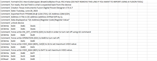
Q3: How do I unlock the device?

Q4: How do I add device unlock to the configuration script generated by the Fusion Power Designer?

  • Q1: How to calculate and set the value of VIDO_MAX(BDh[0] + BEh[7:0])

    The VIDOMAX_L command together with the bit[0] in (BDh) EXT_CAPABILITY_VIDOMAX_H forms a 9-bit register to set the maximum value of (VID+Offset) allowed via SVID. Setting the 9-bit VIDo_MAX register to 17E (hex) value reaches the maximum possible (VID+Offset) value with 8-bit register for each (VID unsigned, offset signed). Exceeding VIDo_MAX with (VID + offset) causes a REJ (Reject) response for individual rail SVID requests and a NACK response for all-call SVID requests.

    To start, choose a your maximum voltage. For this example we'll choose 1.3V.

    Use the equations below to calculate what the decimal value of should be, where the step size refers to the SVID Protocol chosen:

    10mV Step:
    VIDO_MAX(V) = VIDO_MAX(d)*0.010 + 0.490

    5mV Step:
    VIDO_MAX(V) = VIDO_MAX(d)*0.005 + 0.245

    We'll use the 5mV step equation to find our VIDO_MAX value in decimal. In this case, plugging 1.3V into VIDO_MAX(V) gives us a VIDO_MAX(d) value of 211.

    If you are using the fusion GUI, you can type this value into the register field on the TPS544C26 Device Specific page seen below: 

    Otherwise, you will have to convert the decimal value into binary and program it into BDh[0] + BEh[7:0] manually.

  • Q2: What is the difference between I2C and SVID? Which one should I use?

    SVID is a protocol developed by intel to streamline communications between their devices and voltage regulators. SVID is needed for Intel VR12, VR 12.5, VR13, VR14, IMPVP8 designs. It is separate from I2C. SVID is only available in designs where an Intel CPU is the controller. I2C is an open source communication protocol that can be implemented by any microcontroller.

  • Q3: How do I lock/unlock the device?

    Most registers on the device are locked to prevent accidental changes. To unlock the device, you will need to send a two byte "password" to register B1h. Please ask your TI representative for the device password. You can input the password through standard I2C communications, or you can enter it in the SAA tool/Device specific "registers" panel on TI's Fusion Power Designer.

    In this example, I'm using the device specific "registers" tab on Fusion Power Designer. Please click on the photo to enlarge it.

    Entering the password may produce a NACK response on both bytes, but if you entered the password correctly, the device will be unlocked. You can test this by trying to make a change to a previously locked register.

    Here's an example using the I2C/SAA Tool available on the Fusion Power Designer. The value sent to B1h in the image below is an example and is NOT the correct password combination.  Please click on the photo to enlarge it.

    To lock the device, simply send a value that is not the correct password to register B1h and the device will relock. Alternatively, you can do a power cycle. Just remember to save your configuration to the NVM before doing so, as any unsaved changes are lost when power cycling.

  • Q4: How do I add device unlock to the configuration script generated by the Fusion Power Designer?

    The Fusion Power Designer allows the user to import and export device configurations. In the current version, it does not automatically generate the password to unlock the device when exporting a configuration, which leads to failures when importing to other devices. The current version can, however, ignore NACKs to the B1h register, allowing the user to modify their configuration file and add lines for the password. This greatly increases productivity, and is recommended. Otherwise, the user will have to manually unlock the device before importing a configuration file. 

    The photo below shows how the configuration file (with byte breakout enabled) should look when adding lines for the B1h password. The values in the image below are examples and are NOT the correct password combination. Please click on the photo to enlarge it.

    Note that the code to unlock the password is the first command to be sent. Anything before it may result in a failed import. The second column will need to be changed to match the device address that you are trying to import to.

    Please note that if you are importing to a device with a different address, you will have to alter the I2C_ADDR (A2h) register in the configuration file to match the address that you are importing to, as well as all of the addresses in column two of the configuration file, otherwise the configuration will fail to import.