This thread has been locked.

If you have a related question, please click the "Ask a related question" button in the top right corner. The newly created question will be automatically linked to this question.

BQ25303J: Unknown blink rate and fault

Part Number: BQ25303J

Hi,

I have created a charging circuit using the BQ25303JRTER. The dataqsheet states the following at charge faults:

1. VBUS input overvoltage

2. TS cold/hot faults

3. Battery over voltage

4. IC thermal shutdown

5. Safety timer expiration with battery coltage below recharge threshold

6. ICHG pin open or short

This should lead to the blinking of a led (connected to the STAT pin) at 1 Hz with a duty cycle of 50%.

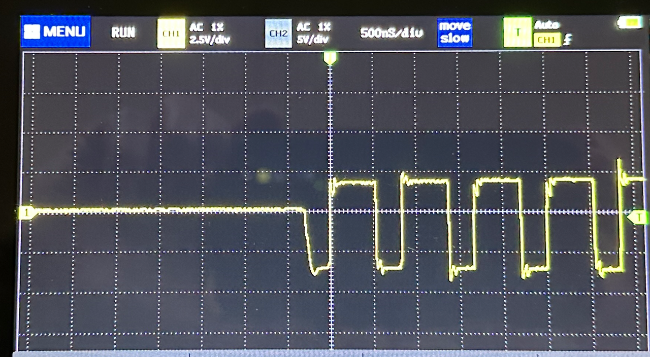
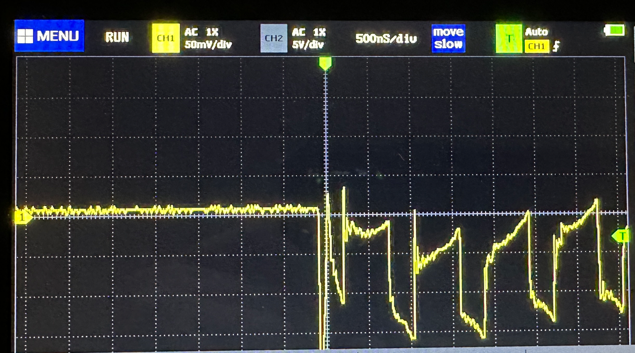
I found that some batteries in my circuit charge and some don't. To my knowledge there is no difference between these batteries (same model and age) and they function fine in another charging circuit using non-TI parts. Whenever a battery refuses to charge, the BQ25303 is blinking the led, but not at a 1 Hz rate. Instead, the blinking rate is much higher, I estimate it at 30 Hz maybe even more. I find no other description of blinking rates in the datasheet so I don't know what the IC is trying to communicate, if it is communicating anything at all.

What does the pulling down of the STAT pin at an estimated 30Hz with duty cycle of 50% mean?

  • I forgot to add that the 1 Hz blinking seems to do its job fine otherwise. If I remove the battery or tinker with the thermistor protection to trigger a cold/hot fault, it indeed starts blinking at 1 Hz.

  • Hi,

    Before debugging, could you please confirm your design follows Figure 10-1. Typical Application Diagram on the d/s?

    Thank you very much,

    Ning.

  • Hello Ning,

    ofcourse, I should have added this immediately:

  • Hi,

    The STAT pin output indicates the charging status of charging (LOW), charging complete or charge disabled (HIGH) or charging faults (BLINKING). The device may switch between charging (LOW) and charging complete or charge disabled (HIGH) which look like the STAT pin blinks at some frequency. Please monitor VBUS (voltage at VBUS pin), IVBUS, VBAT (voltage at BAT pin), IBAT on a scope and check what's going on,

    Thank you very much,

    Ning.

  • My VBUS is an expected 5.1V. VBAT does not seem to go above the battery voltage. I've seen it reach IBAT of 1.1A when it managed to start charging, and on that occasion it did manage to rise the VBAT voltage to 4.1V.

    I'm getting a feeling my charger is not capable of supplying the circuit, even though in theory it should be able to. Can a too low IBUS cause a failed charge cycle and the fast blinking of the STAT pin?

  • Hi,

    If the input power is unable to support the load power, it is possible that the device stops charging. Please refer to below for the details.

    To meet maximum current limit in USB spec and avoid over loading the adapter, the device features Dynamic Power management (DPM), which continuously monitors the input current and input voltage. When input source is over-loaded, either the current exceeds the input current limit (IINDPM) or the voltage falls below the input voltage limit (VINDPM). The device then reduces the charge current until the input current falls below the input current limit and the input voltage rises above the input voltage limit.

    When the charge current is reduced to zero, but the input source is still overloaded, the system voltage starts to drop. Once the system voltage falls below the battery voltage, the device automatically enters the supplement mode where the BATFET turns on and battery starts discharging so that the system is supported from both the input source and battery.

    Thanks,

    Ning.

  • I have tried the system with a bigger powersupply but to no avail. The stat pin keeps blinking and the battery is not being charged. I borrowed a simple oscilloscope but I do not know how to interpret it. I have taken a measurement before and after the inductor. The power supply appears to give a pretty undisturbed 5V.

    Before the inductor:

    after the inductor:

    The 21700 battery connected to the system had a voltage of 3.5V.

    I discovered there seems to be a charge current of 60-70mA when the stat pin is flickering. The datasheet states this is the precharge phase, I reckon it keeps switching between charging and precharging. Why would this be?

    I feel like I'm getting closer: When connecting the oscilloscope probe to the ICHG pin (before the 14.3k resistor), the STAT pin is pulled down immediately indicating that the charge cycle has begun. When measuring with a regular multimeter, the STAT pin sometimes,starts blinking at 1hz indicating a fault. Most of the time nothing changes and the stat pin keeps flickering.

    Something is up with the ICHG pin. Perhaps my resistor is too small? Maybe there is some capacitance problem?

  • Hi,

    Did you set up Richg per 10.2.1.2.2 Charge Current Setting on the d/s? Referring to 8.5 Electrical Characteristics table on the d/s, ICHG set at 1.72A with RICHG = 23.2kΩ or 1.0A with RICHG = 40.2kΩ or 0.5A with RICHG = 78.7kΩ. When ICHG pin is pulled to ground or left open, the charger stop switching and STAT pin starts blinking.

    Thanks,

    Ning.

  • I want a charge current of max ~2.8A, so I found a KICHG value of 39800 in Figure 8-5. Given that RICHG = KICHG/ICHG, I found I would need a resistor of 14.2k from the ICHG in to GND. Because 14.3k was the closest resistor available, that is the value I chose.

    What do you mean by d/s? -edit ah, datasheet obviously

  • Hi,

    D/S refers to datasheet. Did you try RICHG = 78.7kΩ? Did you get 0.5A charge current?

    Thanks,

    Ning.

  • No, I only used the 14.3k resistor. The circuit works, but only if I connect my oscilloscope probe to the ICHG pin. Oscilloscope internal resistance is like 10Mohm so that doesnt lower the value significantly.

    Why would the circuit work when I connect my oscilloscope, but won't when it is not connected?

  • Hi,

    Could you please double-check the resistor soldering?

    Thanks,

    Ning.

  • Hello Ning,

    I have replaced the resistor and checked the soldering but to no avail. I did manage to get it to work, but I don't understand why:

    The problem is obviously at the ICHG pin because the circuit works when I connect an oscilloscope to that pin. I soldered a 10pF ceramic capacitor over the resistor and presto: It works!

    I don't understand why because the datasheet specifically states that 'No capacitor is allowed to connect at this pin'. The circuit doesn't work with larger values (e.g. 10uF), but the only way I get it to work is with at least -some-  added capacitance.

    Why would the circuit work with a capacitor at the ICHG pin even though the datasheet states it does not?

  • Hi,

    Have you tried on multiple boards?

    Thanks,

    Ning

  • Yes, I have 5 units and in none of them the ICHG pin does what you would expect

  • Hi,

    Please double-check the custom board. We are unable to observe the behavior on the EVM.

    Thanks,

    Ning.