This thread has been locked.

If you have a related question, please click the "Ask a related question" button in the top right corner. The newly created question will be automatically linked to this question.

BQ34Z100-G1: Design issue

Part Number: BQ34Z100-G1

Hi team,

Design with following questions:

1) The chip captures batteries up to 48V, and the official reference board is designed with a number of chips. Is it possible to simply design with the BQ34Z100-G1?

2) The BQ34Z100-G1 design is shown in the following figure:

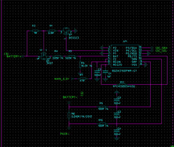
3) One battery is B+ B-, where is Pack- connected?

4) 11 pin of the chip recommended NTC-10K, is it for temperature detection? If not being used, can the pin be left floating?

5) BQ34Z100-G1 and GD Single Chip go I2C Communication, is it required additional pins?

6) 1 3 is actually an LED output pin, what do these LEDs mean? It doesn't have to be grounded right?

Could you help check this case? Thanks.

Best Regards,

Cherry

  • Hello Cherry,

    1. bq34z100-G1 can be used as top of stack gauge. If cell balancing is not required, then this gauge is well suited

    2. Not a question

    3. Pack- is connected to load/charger negative terminal

    4. Temperature sensor is required for accurate readings. It should not be left floating

    5. I did not understand this question. I2C pins are brought out from the bq34z100-G1 

    6. TRM section 3.9 LED Display described use of LEDs