A related question is a question created from another question. When the related question is created, it will be automatically linked to the original question.
If you have a related question, please click the "Ask a related question" button in the top right corner. The newly created question will be automatically linked to this question.
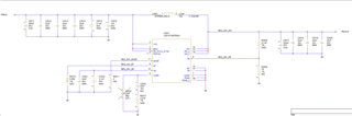
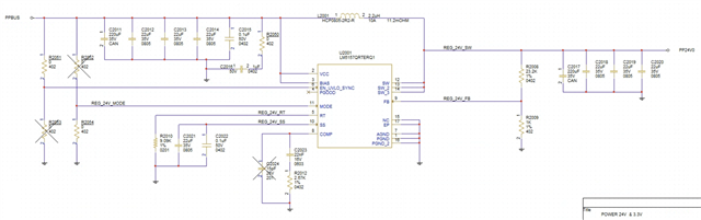
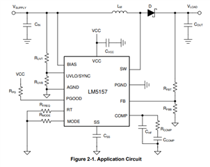
The schematic seems to be ok, but I would recommend changing some components for a first prototype:
- Add a resistor in series to the VCC capacitor as mentioned in the datasheet.
- Add a resistor divider to the UVLO input to have the possibility to change the UVLO voltage if needed (you can populate just the upper one with 0 ohm at the beginning). Starting at the lowest UVLO voltage means high current at startup.
- Add a resistor to a high voltage to the MODE pin. If you do not need it fine, but if you find out you need it, it is good to have the place to add it.
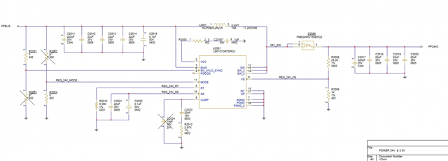
Here is with the updates you asked for, please provide feedback. I ran the calculator on my inductor and current ripple ratio will be ~11%, which sounds good to me.