This thread has been locked.

If you have a related question, please click the "Ask a related question" button in the top right corner. The newly created question will be automatically linked to this question.

LM25085: Abnormal Transition period when charging a super capacitor with a ideal diode switch; Cannot immediately restart during current-limiting mode

Part Number: LM25085
Other Parts Discussed in Thread: LM3102, LM25011, LM3100

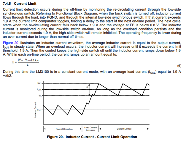
Hi, I have an urgent issue about the LM25085:

Circuit Description: LM25085, as the first-stage Buck chip, is connected to the supercapacitor through the MOS driven by the LM74701 ideal diode controller to charge the supercapacitor.


Function Description: At the beginning, the supercapacitor is charged from 0V through the body diode of the MOS (Q4 in the schematic diagram), and the MOS (Q4) is turned off; later, when the output voltage of the LM25085 rises to the turn-on threshold of the MOS (about 3V), the MOS is turned on, and the charging path is switched from the body diode to the MOS.


Phenomenon Description: However, in the customer's application, it is found that when the path is switched from the body diode to the MOS, the circuit does not work normally, the circuit enters a similar hiccup mode (current-limiting mode), and the MOS drive waveform driven by the LM25085 is also abnormal. However, after a period of time, the system returns to the normal state, exits the hiccup mode (current limiting mode), and the supercapacitor voltage continues to rise. And during the hiccup mode, the switching state of LM25085's MOS seems abnormal. Even though the inductor current has been reduced to 0, LM25085 still does not return to the switching state, and restarts after about 100-200us.

The key waveforms are given below:

Channel 1: The output voltage (Capacitor Node) of LM25085; Channel 4: The waveform of the inductor current. It can be found that there is a period of abnormal state (like hiccup mode/ current limiting mode)

Channel 1: The output voltage (SW Node) of LM25085; Channel 4: The waveform of the inductor current. It can be found that even though the inductor current has been reduced to 0, LM25085 still does not return to the switching state, and restarts after about 100-200us.

Thus, my questions can be concluded that:

1.Why there is an abnormal transition period of the LM25085 when the path is switched from the body diode to the MOS.

2.Why even though the inductor current has been reduced to 0, LM25085 still does not return to the switching state, and restarts after about 100-200us. (Which should be restarted immediately)

  • Hi Matt,

    It seems like the system is hitting current limit as well as is unstable. In addition it seems like this solution to charge up a supercapacitor will not work since it does not have a valley current limit. The on-time will be very small, and as a result, very little current is delivered to your supercap load. LM25085 only has peak current limit detection.

    A better charging solution will need a peak and valley current limit to control IOUT to deliver stable current to the output. With peak and valley limits, the HS FET of the device will turn on with a fixed on time, and then be able to turn off once valley current limit is reached. Some devices that implement this would be LM3102, LM3100 or if you'd like the non-synchronous version, LM25011.

    Please see section 7.4.5 on the LM3100 DS below:

    Alternatively, you can also use a CVCC topology with altered control loop to charge a supercapacitor. Please see the attached link to the blog: https://e2e.ti.com/blogs_/b/powerhouse/posts/how-to-design-a-simple-constant-current-constant-voltage-buck-converter

    Hope this helps.

    Regards,

    Henry

  • Hi Henry,

    Thank you for your replay,

    However, maybe I want to repeat my questions:

    1. Why even though the inductor current has been reduced to 0, LM25085 still does not return to the switching state, and restarts after about 100-200us. (Which should be restarted immediately).

    According to the datasheet, the current limit off-time should be calculated as the following equation:

    And based on the circuit of my customer, the off-time should be 4.5us, instead of the actual 100-200us.

    2. Why there is an abnormal transition period of the LM25085 when the path is switched from the body diode to the MOS.

    Since there is no load transmission or filter transmission, the operating condition seems no-change.

    Regards,

    Matt.

  • Hi Matt,

    The behavior does seem to be abnormal. It would be nice to isolate the circuit from the load and test it independently.

    I would suggest to remove Q12, Check Q9 FET rating, disconnect everything right side of C8 and check that the controller is working correctly first and is stable.

    Are you able to provide a layout? I'd like to check the routing of the current sense.

    I'd like to reiterate this device will not regulate the current for charging a capacitor accurately – the average current will change based on the Voltage across the SC as VFB/ToffCL adjusts.   valley current limit is a better way to control the current in a short circuit scenario.

    Regards,

    Henry

  • Hi Henry,

    I'm communicating with my customer about your advice, Thank you, and I will give my response soon.

    Regards.

    Matt.

  • Hi Matt,

    Thanks and looking forward to your reply.

    Regards,

    Henry

  • Hi Henry,

    This problem is solved. Thank you for your reply~

    Best Regards

    Matt Qi

  • Hi Matt, Which method did you use to solve the issue?

    Thanks,

    Henry